
|
Shane's R2 Build Log
|
|
|
Shane's R2 Build Log
|
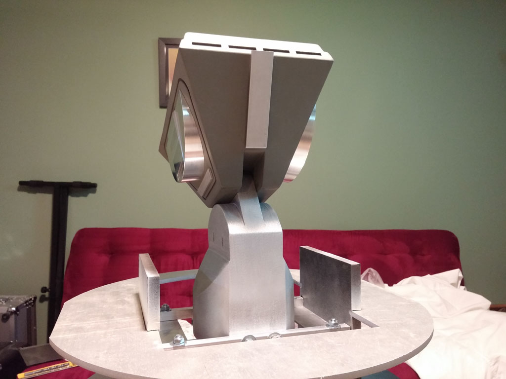
Mounting the Center AnkleFor a few months I had a pretty good idea of how I was going to attach the center ankle to the frame. It involved some wood, a couple of lengths of angle stock, and about 2 hours of my time. Unfortunately when the day came, my plan didn't quite work out. As soon as I started measuring things, I realized quickly that I needed a plan B. So I looked around at what spare materials I had and came up with a pretty decent mounting kit (or so I think). I had already purchased a length of aluminum angle stock from Lowes for plan A. It was 1.5" width on both axes and 1/8" thick. I also had a couple of pieces of 1/2" solid aluminum square stock that I had accidentally purchased from OnlineMetals.com. What I needed that I didn't have was a bunch of 1/4" screws, nuts, and washers. So that meant a trip to the hardware store. Cutting the Pieces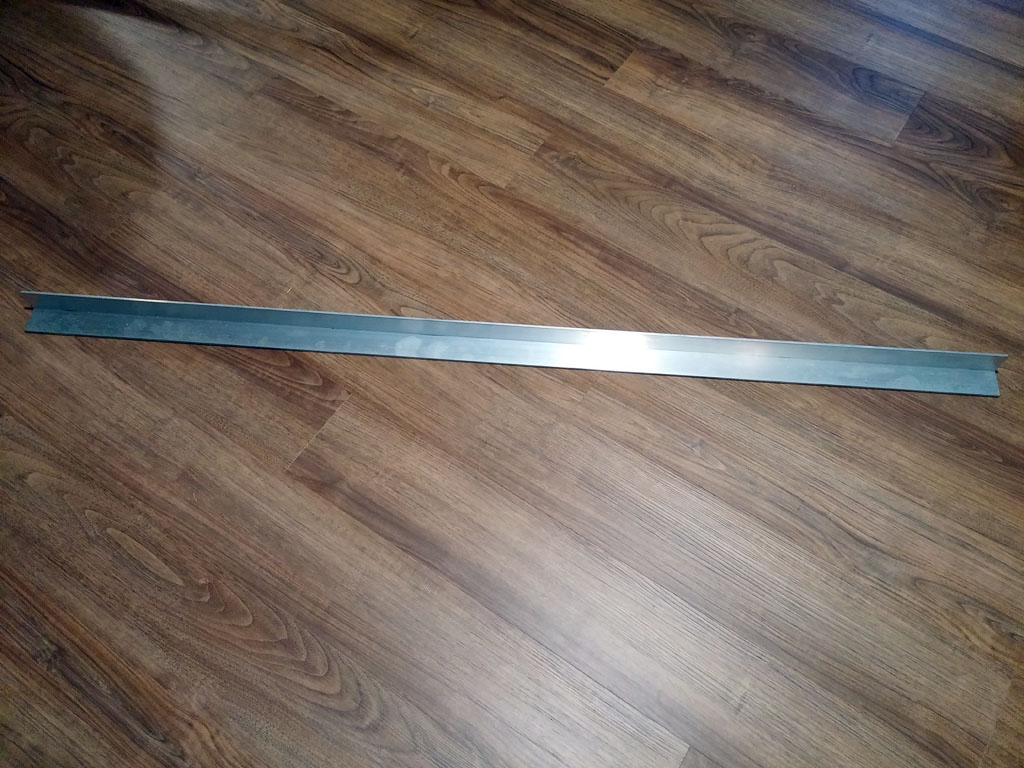 The first thing I did was cut the angle stock down to size. I wanted to have two angle brackets attach horizontally to the vertical supports in my A&A frame. These supports measured 6 1/8" wide. So I cut two pieces to length. The second thing I did was cut the solid 1/2" bars. The gap between my vertical supports measured at around 9 inches. I cut two pieces to this length. After testing fitting them into the frame, however, I realized the gap within the frame wasn't as uniform as it could be and I really needed to be able move these things around. So I ended up shaving a little bit off the bars. They ended up coming in at 8 7/8". All pieces were cut using a metal-appropriate blade on a miter saw. Drilling HolesNext I worked on drilling all the holes that attach the pieces together. I opted for 1/4" holes because I was dealing with 1/2" aluminum stock. Time will tell if either the 1/4" bolts or the 1/2" stock aren't strong enough. Using Adobe Illustrator, I drew out some drilling templates. I then printed them, cut them up, and attached them to my pieces using some 3M adhesive spray.   I used a drill press to drill out the 1/4" holes. Test FitWith all the pieces cut and drilled, I then test-fit everything. 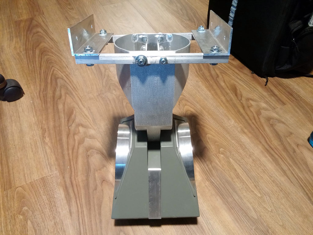 Something peculiar I noticed that may not be a big deal is that one of the mounting holes on one side of my middle ankle as slightly lower than the other. This results in a, what I hope is barely noticeable, crooked posture. If this looks to be a problem, I can probably correct it with some extra washers where the bar meets the angle bracket. Note that I mounted the solid bars beneath the angle brackets. The reason for this is that I wanted the upward force to be directed against the full width of the angle bracket and not just the part of the bracket that extends outward. My thought was that if I did things the other way, the angle bracket might be prone to bend. Of course, I have no actual idea if that would happen. But it made sense in my head at the time. When I was satisfied that things more or less fit well together out in the open, I took apart the mounting kit and reassembled it inside the A&A frame. For this step, I also attached the outer legs, ankles, and feet. I needed to see where the angle brackets would need to be positioned within the frame. For this, everything needed to be level and straight. I also didn't have my foot drives mounted within the outer feet. So once I determined the optimal position for the angle brackets, I subtracted an inch as that's the ground clearance I'm going for. I then drilled out 1/4" mounting holes on the frame. Final AssemblyI took a file to all the cut pieces to ensure there was nothing left to cut me (I should have done this ealier, but alas). I also removed all of the drilling templates with some Goo-Gone. For final assembly, I removed the outer legs and flipped the frame upside on a table. I mounted the angle brackets to the frame first. The 1/2" solid bars were mounted to the ankle next. And then finally, the bars were attached to the angle brackets.
 Everything then got flipped back over. I then reattached the outer legs and propped the whole thing up on some spare 2x2s. This will have to do until the foot drives are mounted. 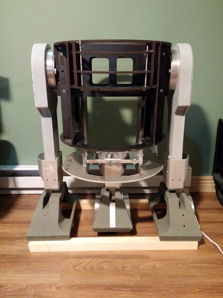 |