|
Shane's R2 Build Log
|
|
|
Shane's R2 Build Log
|
Mounting The Warp Drives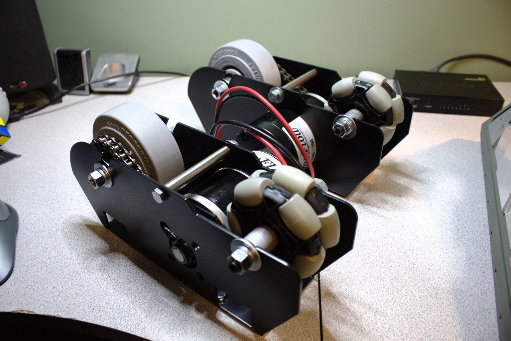 I think most folks mount the Warp Drives by drilling and running bolts straight through the U-channel on the foot shells and into the drive brackets. I didn't have the heart to drill out my beautiful foot shells. They're too nice and too expensive. I instead approached mounting the foot drives in a similar way as I did the middle foot wheel assembly, but with a few small variations. The first step was figuring out how much I needed to raise the foot shell over the foot drive so that I could get the ground clearance I needed. For the middle foot, I ended up with right around 1" of ground clearance. So that was my target for the outer feet too. The foot drives alone only provide around 1/2" space, so I'd need something else sitting between the foot drives and the foot shells to account for the other 1/2". So I ordered a couple of bars of 1.25" x .5" solid aluminum stock from OnlineMetals.com (I love this store). Once they arrived, I used a miter saw to cut them down to match the length of the drive bracket.  Next, I created a drill template for both the drive bracket and the aluminum bar.  For the aluminum bar, I drilled and tapped two 5/16"-18 holes 1.5" from either end of the bar. 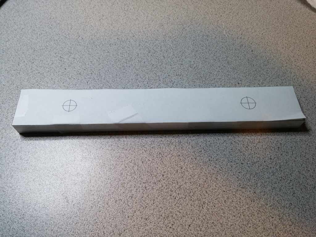


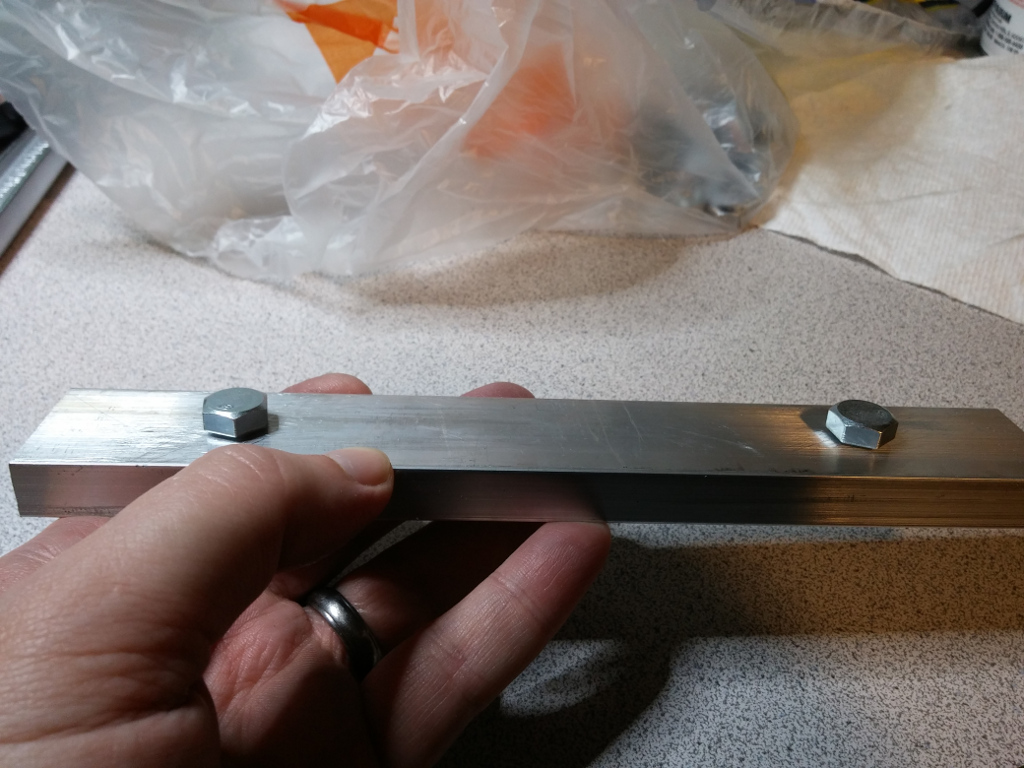
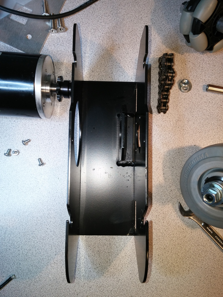
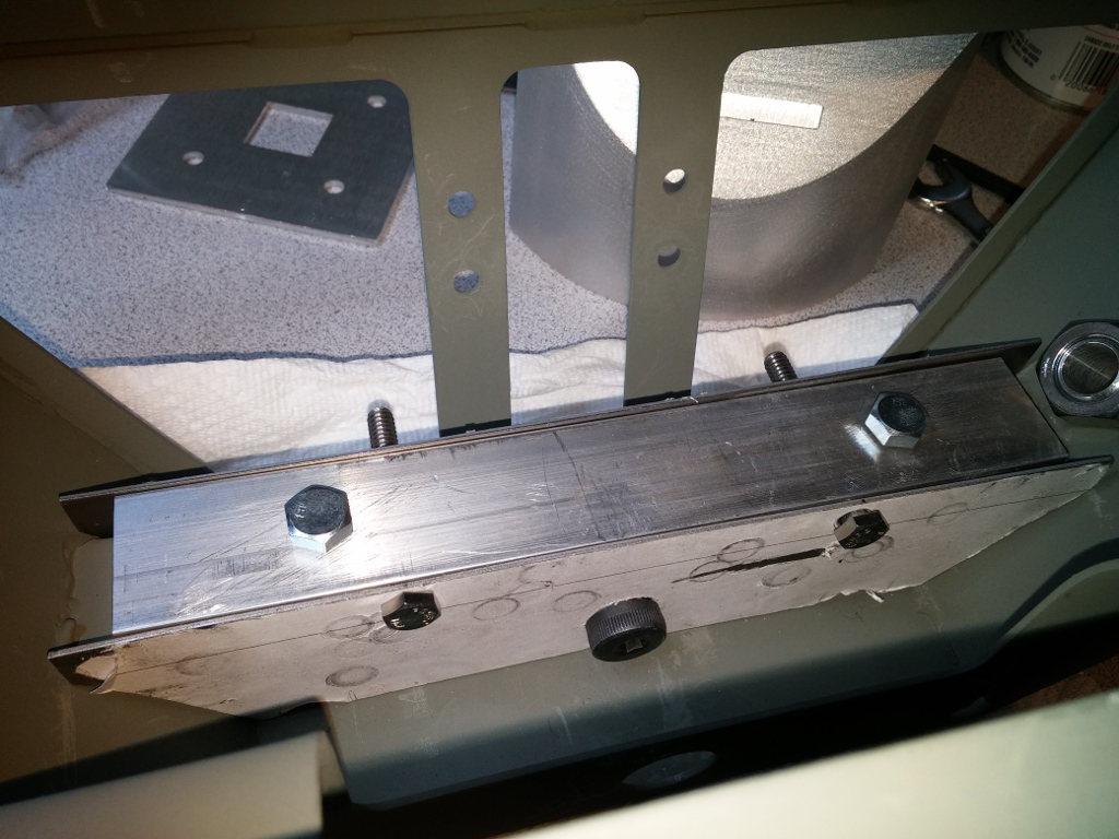
In the last photo above, I've screwed in two 1/2" bolts just for testing the threading. These bolts are actually used to attach the bar to the foot drive bracket, which I show later. Before drilling into the drive bracket, I had to disassemble the foot drive. I didn't want any bits of metal to get into anywhere it shouldn't. Fortunately, the foot drives were super easy to disassemble. I removed the VEX wheel first, then the Colson wheel and bracket spacer, then the motor, and finally the chain. 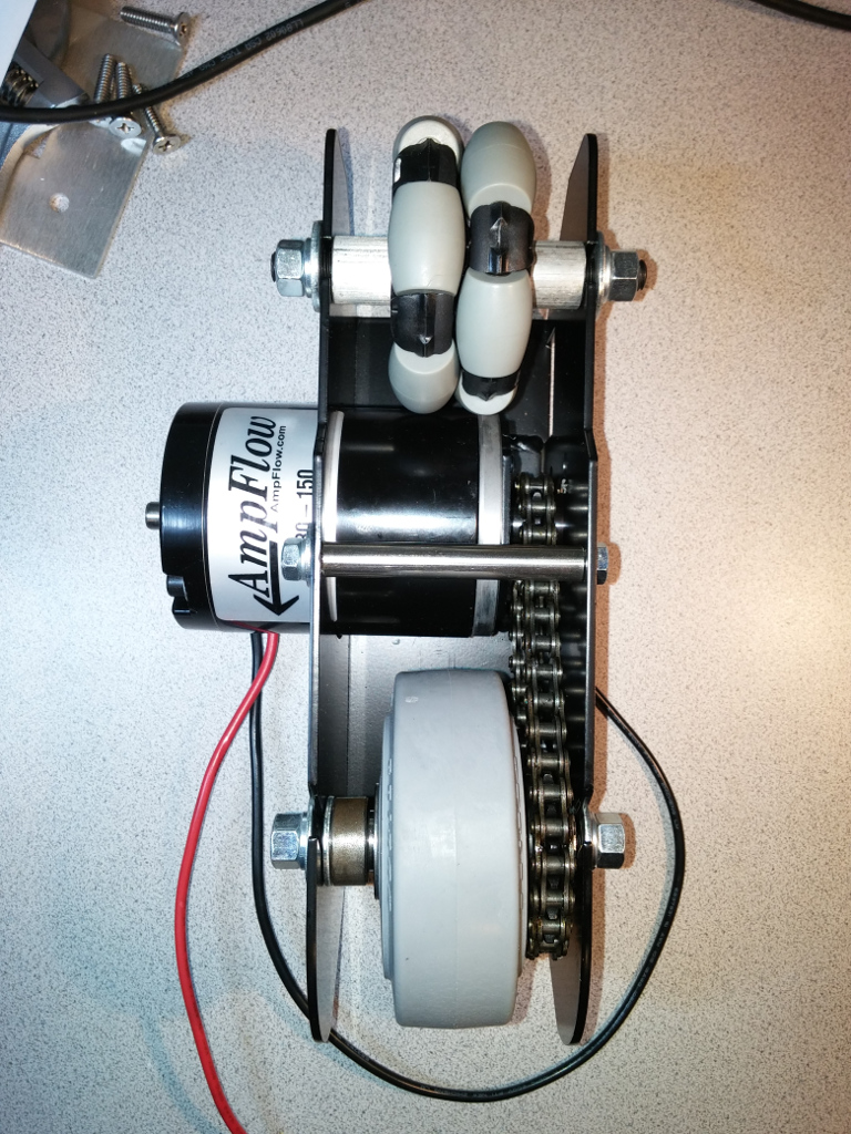

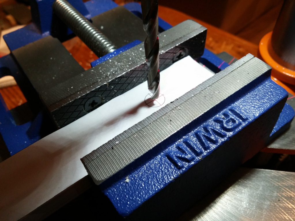
I carefully taped the drill template to the top of the drive bracket, measuring carefully that holes will be positioned where they're supposed to be. I then drilled the holes and test fit the spacer bar. 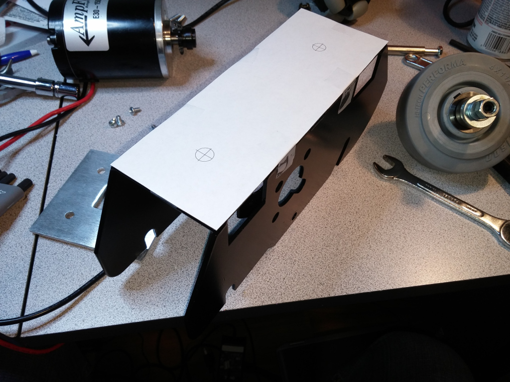 Next up, I needed to build a bracket that would allow the foot drive to actually attach to the foot shell. I decided to do things a little differently to what I did with the middle foot. This time I drilled holes straight through the sides of the spacer bar, which allowed me to use only two bolts for attaching the spacer to the bracket. These holes would NOT be tapped. I would instead use some Nyloc nuts. I created another drill template for the spacer. This time I'd be drilling 1/4" holes straight through the sides of the bar. These holes were offset 2" from the outer edge. 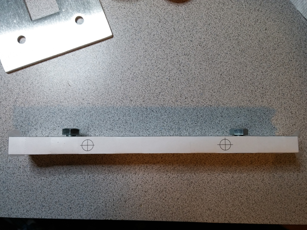

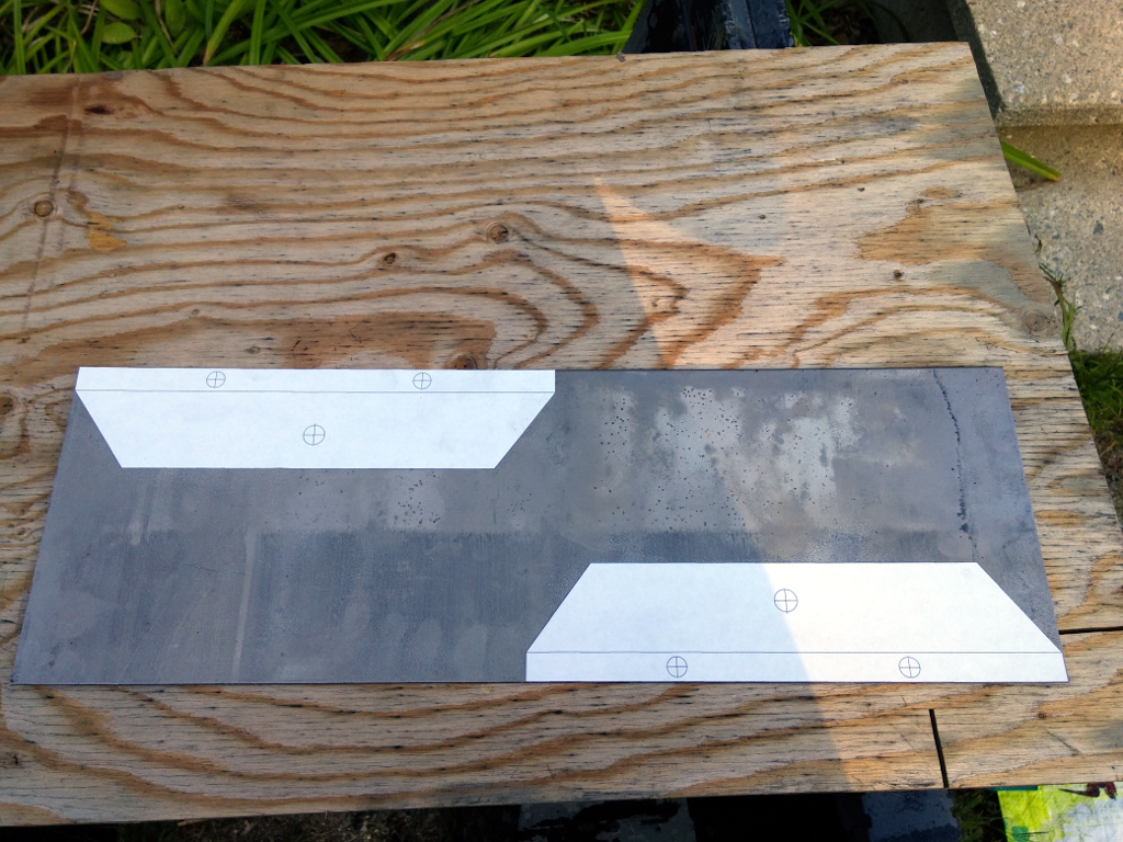
I then created the mounting bracket. For this, I picked up a piece of 6in. x 16ga x 18in. steel sheet metal from Home Depot. Based on measurements I took from the inside of the foot shell, I designed a cutting/drilling template in Illustrator and attached it to the sheet metal using a 3M adhesive spray. I then used a jigsaw with a metal cutting blade to cut out the bracket sides. 


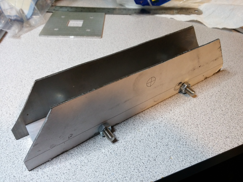
Using a stepper bit, I drilled out the bolt holes on the mounting bracket sides. I used a file to knock out any burs. And then I test fit the mounting bracket with the previously drilled spacer bar and the foot shell. To attach the mounting bracket to the spacer bar, I used whatever 1/4" bolts that were 2" long I could find at Home Depot. The threading didn't matter so long as I had matching nuts. 
Something I realized when trying to test fit the mounting bracket to the foot shell was that the foot shell had welding points that got in the way. I couldn't slide the mounting bracket cleanly over the shell's U-channel. To deal with this, I marked ballpark locations on the mounting bracket sides where the mounting points were and then used by stepper bit to effectively carve out some pretty janky wells that slid around the welds. It didn't need to be pretty. The welds weren't consistent in size and shape anyway. 
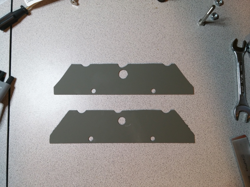
Once everything seemed to fit ok, I took it back apart. I used a file to clean up the edges on the mounting bracket side pieces. I also used some Goo Gone to get rid of the template. Because these pieces were steel, I also gave them a coat of self-etching primer (the same as I used on the footshells) to keep them from rusting. 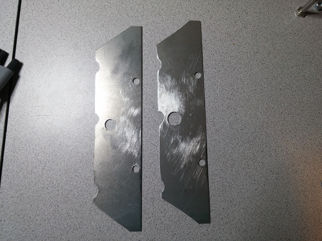
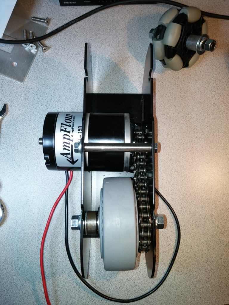
I reattached the spacer bar to the foot drive bracket. And then reassembled all of the foot drive "guts" in the reverse order that I took it apart. I should note that this time when attaching the spacer bar to the foot drive bracket, I applied some LocTite to the bolt threads. This, I hope, will keep those stubby little bolts from working themselves loose as R2 scoot around. (fingers crossed) 
I then attached the mounting bracket sides to the foot shell. Because the ankle bolt is used to secure these in place, I needed to actually attach the ankle to the foot. I did so loosely at first so that the mounting bracket had some give. I then slid the drive assembly into the foot shell, the drive wheel oriented to the front of the foot shell. I slipped the 1/4" bolts through the bracket and tightened everything up, including the ankle bolt. 
At the time of this writing, everything seems pretty sturdy. I haven't, however, had a chance to try it out just yet. I'll have to wait until I get some of my electronics in order to prove it out. Once I do, and if it doesn't work out that well, I'll update this page appropriately. |