|
Shane's R2 Build Log
|
|
|
Shane's R2 Build Log
|
Attaching Shoulder Flange to A&A FrameAttaching JAG-compatible shoulder flanges to the A&A frame wasn't as straightforward as I had hoped. The A&A guys made the bolt circle on their JAG stops considerably smaller than that of the Worr shoulder flange I was using. You can see both the A&A PVC JAG stop and the aluminum shoulder flange in the photo below. 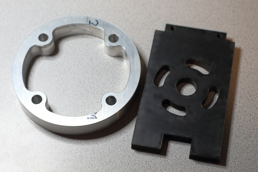 It wasn't immediately obvious to me how I was going to mount the flange, and thus the legs, to the frame. I had a couple of missteps in solving this. I'll detail the first and biggest misstep below because it was the one with the most time and money invested in it. I did get there in the end, though. Once Step Forward, Two Steps BackIn my travels, I stumbled across another builder with the same frame and flange as me. His solution was to machine a well in the flange for a second set of bolts that would connect the flange to the A&A JAG stop. The legs would mount to the flange using the original holes. It was certainly an interesting approach. But I didn't have the resources or the expertise to accomplish the same thing. I'd need to do something different.I saw that I basically had to choose one of two paths - 1) Replace the JAG stops with something of my own design, or 2) fabricate some sort of adapter. Both seemed like a bit of work. I (WRONGLY) opted for an adapter. I ordered two 6" diameter 1/8" thick aluminum disks from MetalRemnants.com ($14.00 + $12.75 shipping (ouch)). I probably could have gone a bit thinner, but I wanted something that could handle the stress the legs would be placing on the entire shoulder area. 6" is actually a smaller diameter than the shoulder flange, but it was sufficient for the bolt locations and it should be hidden anyway. 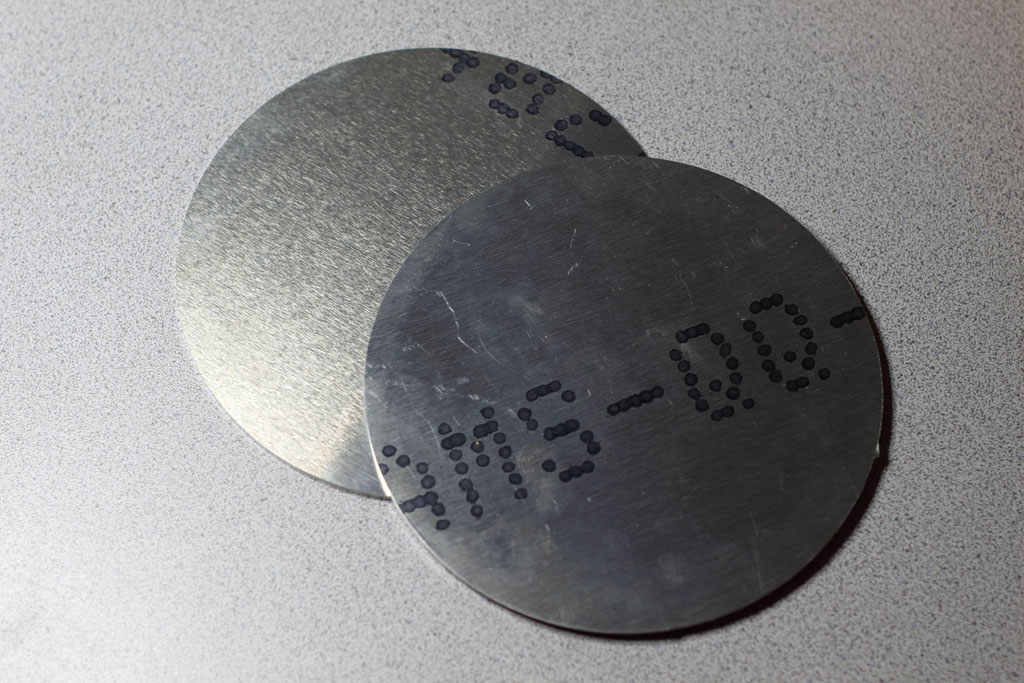
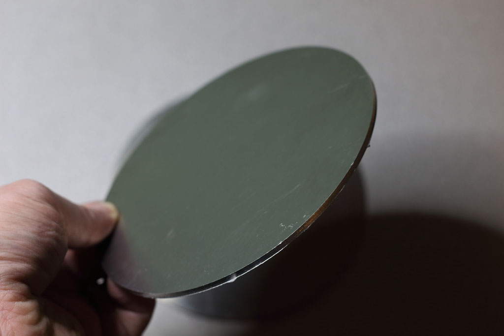
I next created a drill template in Adobe Illustrator, attached it with some spray adhesive, and then drilled everything out. All holes accommodated 1/2" bolts. The center hole is for the electrical wiring. The inner holes are for the JAG stops. The outer holes are for the flange. 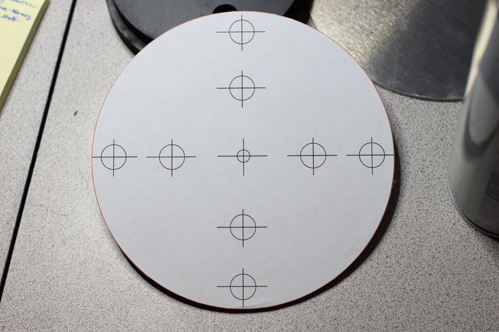
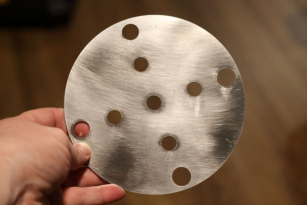
I was pretty proud of this solution. For months I scooted R2 around like this, letting friends and family drive him around the basement (where I work). All the while, I was unaware of a problem that was about to knock the builder-hubris right out of me. The day came to test mount the skins. All I really wanted to do was to make sure the frame and the skins were up to spec. So I wrapped the front skins around the frame, carefully aligning them so that the front cut outs were perfectly centered, and then I taped the skins into place. I took one step back and my jaw hit for the floor. There were awful gaps between the skins and the shoulder flanges.  My first thought was that my 1/8" disks were too thick. But I took some measurements and found the gap was greater than 1/8" in places. Thinner adapters, or even no adapters, wouldn't have mattered. A gap of some size would still exist. I needed to take another pass at this problem. Side Note: To this day, I still haven't learned how the A&A folks make this work. I know a number of builders have used this frame successfully. So it's a mystery to me. I'd be grateful if any of those folks could reach out to me and tell me why this wasn't an issue for them. :-P The SolutionMy final solution was to design a custom aluminum mounting plate for the flange. I considered designing a drop-in replacement for the frame's A&A JAG stops. But after some measuring and experimentation, I didn't feel confident that I could create a workable solution that could accommodate the bolt circle of the shoulder flange, be thin enough to eliminate the gaps, and not actually get in the way of the skins. I decided to throw out the JAG stops and put my mounting plate right against the frame. There would still be a small gap between the aluminum plate and the frame's shoulder plate, which would accomodate the heads of the bolts for the flange and the legs. I iterated on the design a few times before I found one that would work well. Each time, I prototyped it using a piece of plywood. The drawing for the final design can be downloaded HERE. The plates were waterjet cut out of 5/16" aluminum by Big Blue Saw. This is what they looked like fresh out of the box. 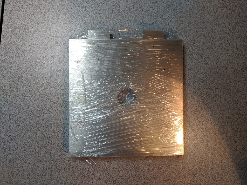
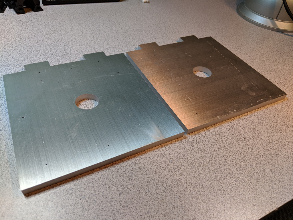
The teeny tiny holes you see on the plate in the photos above were to serve as guides for where to drill. The topmost and bottommost holes were drilled out for 1/4" bolts. I used a 1/2" bit for the flange/leg bolt holes.  
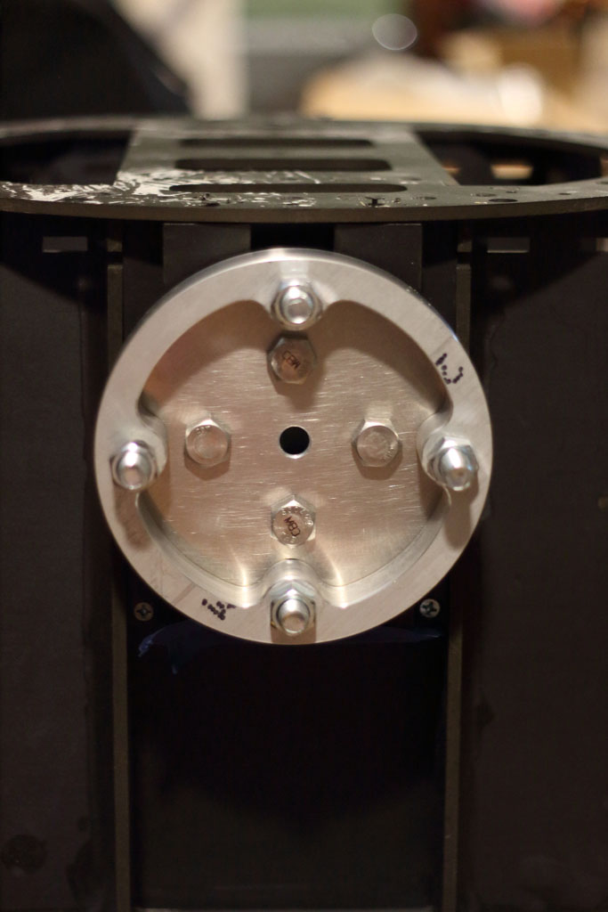
In the photo above, you can see what the shoulder flange looks like when it's attached to the plate. I drilled two sets of leg bolt holes - one for the 2 legged position and one for the three legged position. I expect my droid to always be in three legged mode, but I added the 2 legged holes just in case I change my mind later. I then countersunk the holes for the 1/4" bolts, as the bolt heads will be seated underneath the flange once mounted. 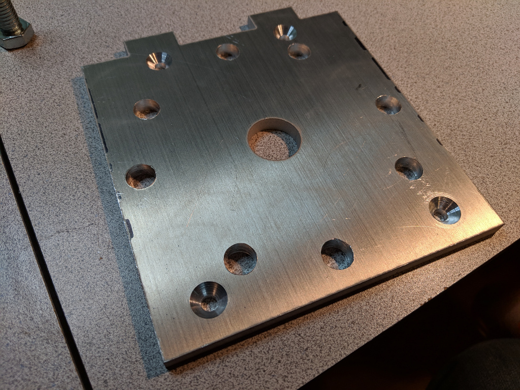
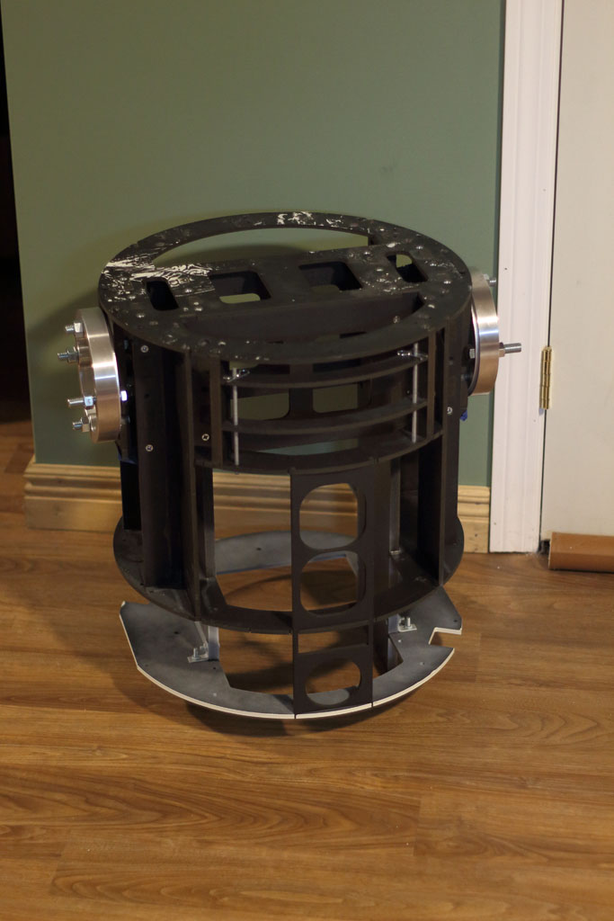
Using the plate as a guide for drill locations, I marked the appropriate shoulder plate locations on the frame using a center punch and then drilled out the 1/4" holes. I slid the 1/2" bolts through the back of the plates and then bolted the plate onto the frame using the 1/4" bolts. I also used some aluminum spacers between the back of the plate and the frame to take some of the stress off the frame's shoulder plate. Once attached to the frame, it looks like so. 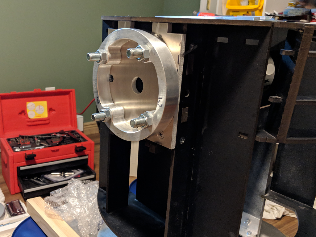
So far, this setup has worked pretty well. I have just the right amount of clearance for the shoulder flanges. If I decide later that I want more flange to show through, I can always throw some washers on the 1/2" bolts. |