My oldest daughter and I recently built one of Mr. Baddeley’s Baby R2s. These units are small, almost cartoonish, radio-controlled R2D2s that are extremely easy to build. And fun! But something missing from the design (at least at the time of this writing) is the ability for these little guys to produce sounds. And what’s an R2D2 with his signature beeps and boops?
For my life-size R2, I incorporated an MP3 Trigger from Sparkfun and paired that with an Arduino. But I couldn’t use that here because the MP3 Trigger is too large. The Baby R2s just can’t accommodate it. So I went in search of something else. And that’s when I came across the DFPlayer from DFRobot.
In this article (the first of three), we’ll be exploring the DFPlayer and beginning our journey into ultimately using an RC radio to trigger audio. If that’s not something that interests you, no worries. This article is focused entirely on the DFPlayer.
DFPlayer
 DFRobot’s DFPlayer is a tiny (~ 21mm x 21mm) module that’s capable of playing MP3, WMV, and WAV audio data. It features a micro-SD slot for your audio files. It can be connected directly to a small speaker (< 3 W) or an amplifier. And it can be controlled a few different ways, including via a serial connection which works well for my particular needs.
Perhaps the biggest selling point for the DFPlayer is its price – $6 as of this writing. Compare that to the SparkFun MP3 Trigger, which comes in at around $50. The DFPlayer is practically a guilt-free impulse buy. In fact, I picked up a 3 pack from Amazon for around $10.
One of the downsides to this module is that there are various models that exhibit different tolerances to electrical noise, which means you might struggle with an audible hiss. Killzone_kid posted a great writeup on the Arduino forums that examines some of the models and makes some recommendations on possible ways to mitigate the hiss. Some of the flavors also apparently have compatibility issues with the officially supported DFPlayer Arduino library, which we’ll look at in a bit.
Here’s the pin diagram for the DFPlayer.
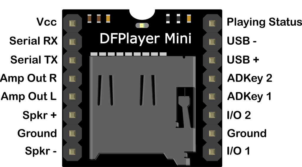
Left-Side Pins
There’s a Vcc pin and a ground pin as you might expect. These pins are used to power up the device. The source voltage must be between 3.2V and 5V.
The Serial RX and TX pins are used to provide a serial interface for controlling the device. It defaults to 9600 baud, 1 data bit, no check bits, no flow control. The serial protocol is detailed in the datasheet. But there’s also an official support library for Arduino called DFRobotDFPlayerMini that implements the serial protocol and provides a high-level interface for controlling the DFPlayer.
The Amp Out pins are for connecting to an audio amplifier or headphones.
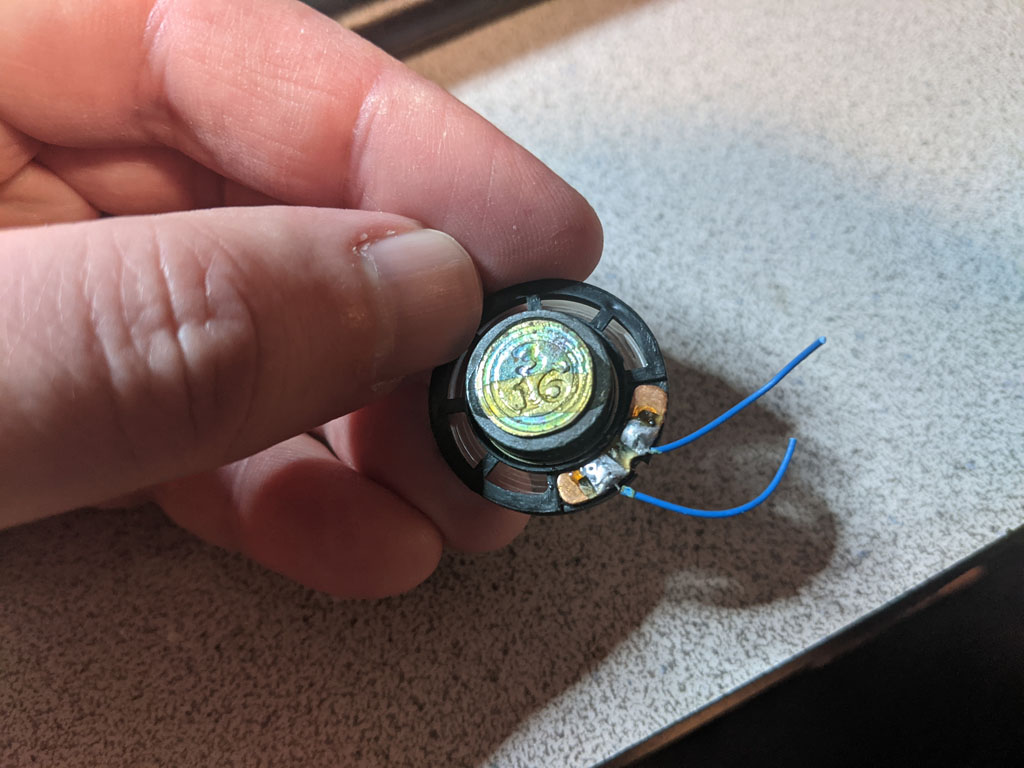
The Spkr pins are for very small speakers – less than 3 watts. This is actually what I’ll be using for my project. I’m connecting the DFPlayer to a small speaker that I harvested from one of my kids’ annoying…er, I mean, broken toys.

Right-Side Pins
On the right-hand side of the pin diagram, you’ll see pairs of pins for I/O and ADKey. These are two other mechanisms for controlling the DFPlayer. We’ll use the I/O pins to test the DFPlayer shortly. But we won’t be using the ADKey pins at all. I won’t be discussing them further. If you want to learn more about them, I advise you to check out the DFPlayer Wiki.
The USB pins allow the DFPlayer to work as a USB device. I haven’t been able to find very much information about this. It’s not discussed much in the DFPlayer manual. Apparently, it provides a mechanism for updating the contents of the SD card from your PC. This could be handy for projects where the DFPlayer ends up hidden away inside of an enclosure that can accommodate a USB connector on the outside. For my project, I don’t need it so I won’t be exploring it. However, if anyone knows where I can find more information about this, please let me know. It could come in handy on another project.
The pin labeled “Playing Status”, referred to as the “Busy” pin, is normally high when the device is idle and goes low when the device is playing audio. The device already has a small LED that lights up when it’s playing files. But if that’s not good enough, you can connect an LED to this pin, or connect it to a microcontroller for more sophisticated behaviors.
Adding Media Files
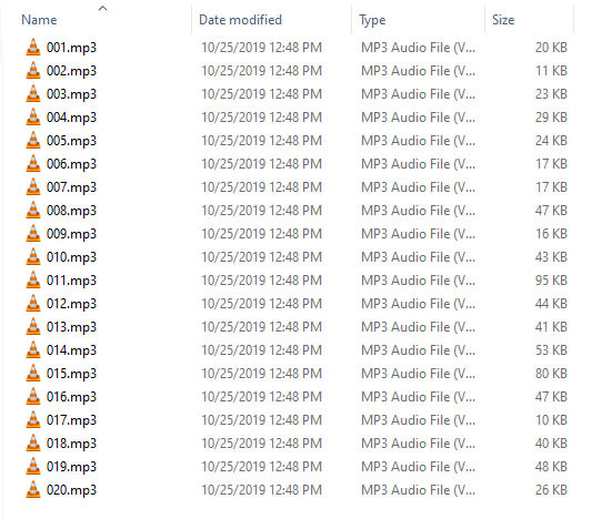
The DFPlayer manual describes the naming of folders and files on the SD card. With regards to files, it specifies names using 3 digit numbers, such as 001.mp3, 002.wav, etc. Folders can be named similarly. I didn’t actually create any folders on my SD card, and it worked just fine. My file layout looks like so.
Testing the DFPlayer
Before doing anything else, I like to do a quick smoke test. This simply involves powering up devices straight out of the box (if feasible) and seeing if any magic blue smoke appears. I also like to note if any LEDs light up, as there’s often a power LED that will indicate the device is at least turning on. In this case, nothing happened. After a bit of reading, I learned that the device’s single LED only lights up when it’s actually playing media. So at this point, I wasn’t sure if it was even powering up. My benchtop power supply said the DFPlayer was pulling a small amount of current, so something was happening.
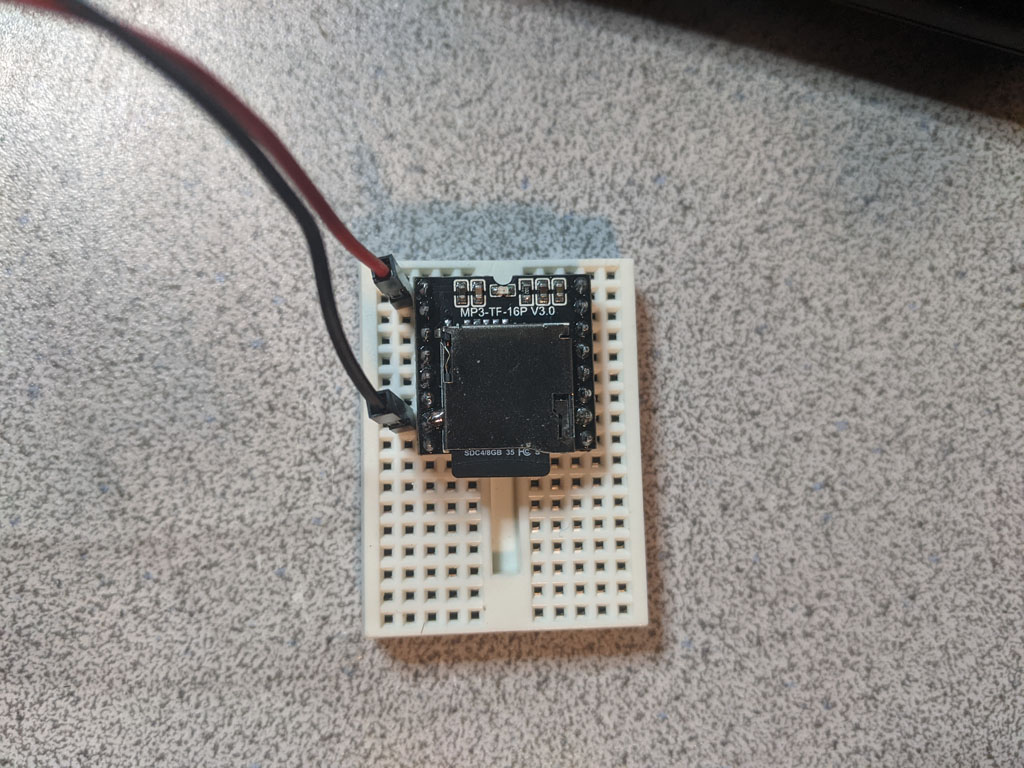
Next, I wanted to see if I could get some sound out of the device. I plugged in my micro SD card and connected my speaker. The I/O pins (9 and 11) were the key to this. Grounding I/O pin 1 for a quick duration will cause the DFPlayer to play the “next” track. Grounding it for a long duration lowers the audio level. Grounding I/O pin 2 for a quick duration will cause the DFPlayer to play the “previous” track. Grounding it for a long duration raises the audio level.
I grounded I/O pin 2 for a couple of seconds to get the audio level all the way up and then quickly grounded I/O pin 1 with a quick tap. The device’s LED lit up and I immediately heard some beeps and boops. The device was working. Success!

Now I knew any issues I might have trying to drive it over a serial connection would be limited to my code and/or the serial interface itself.
Connecting the Arduino
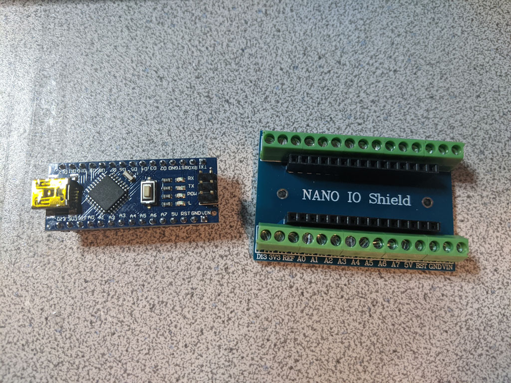
For this project, I used a Nano clone from Lavfin. These come with the pins pre-soldered. When I originally bought this, you could get a pack of 3 from Amazon for around $14. The price has since gone up to $28 as of this writing (presumably, because of supply chain issues).
For testing, I’m used a Nano expansion board. This provides convenient screw terminals.

I connected the DFPlayer to the Arduino using the serial pins of the DFPlayer and digital pins 10 and 11 of the Arduino. The DFPlayer’s RX pin connects to the Arduino’s digital pin 11. The DFPlayer TX pin connects to the Arduino’s digital pin 10.
Why didn’t I use the Arduino’s serial pins? I could have. But the process of writing new code to the Arduino makes use of the UART. So I’d have to disconnect and reconnect the DFPlayer every time I wanted to update the software.
I don’t recommend connecting the DFPlayer Vcc and ground pins to the Arduino’s 5v and ground pins unless you REALLY need to leverage the Arduino’s voltage regulator. This is how I’ve seen it wired in the online examples. It’s convenient, sure. But the Arduino has current supply limitations. Having the DFPlayer and the Arduino connected independently to the power source is the better option.
This is how my DFPlayer and Nano are wired together.

The source code for my Arduino/DFPlayer test is as follows.
#include "Arduino.h" #include "DFRobotDFPlayerMini.h" #include "SoftwareSerial.h" static SoftwareSerial g_serial(10, 11); static DFRobotDFPlayerMini g_dfPlayer; /** * Called when the Arduino starts up. */ void setup() { // We'll use the built-in LED to indicate a communications // problem with the DFPlayer. pinMode(LED_BUILTIN, OUTPUT); digitalWrite(LED_BUILTIN, LOW); // Let's give the DFPlayer some time to startup. delay(2000); g_serial.begin(9600); if (!g_dfPlayer.begin(g_serial)) { // There's a problem talking to the DFPlayer. Let's turn on the LED // and halt. digitalWrite(LED_BUILTIN, HIGH); while(true) { delay(0); } } // Valid values for volume go from 0-30. g_dfPlayer.volume(20); // Plays the first file found on the filesystem. g_dfPlayer.play(1); } // Called over and over as long as the Arduino is powered up. void loop() { static unsigned long timeLastSoundPlayed = millis(); // We're going to iterate through the sounds using DFRobotDFPlayerMini's next() function, // playing a new sound every five seconds. if ((millis() - timeLastSoundPlayed) > 5000) { g_dfPlayer.next(); timeLastSoundPlayed = millis(); } // Consumes any data that might be waiting for us from the DFPlayer. // We don't do anything with it. We could check it and report an error via the // LED. But we can't really dig ourselves out of a bad spot, so I opted to // just ignore it. if (g_dfPlayer.available()) g_dfPlayer.read(); } |
To build this sketch, the DFRobotDFPlayerMini library must be installed. This can be downloaded from GitHub –
https://github.com/DFRobot/DFRobotDFPlayerMini. Installing it is as simple as extracting it to the Arduino libraries directory (e.g., C:\Program Files (x86)\Arduino\libraries).
Line #5 creates an instance of the SoftwareSerial class. I call it g_serial. This is used to emulate a UART over digital pins. I reserved the hardware UART so I could update the software on the Arduino while being connected to DFPlayer. If you’d rather use the hardware UART and the Serial global variable, that’ll work fine too. You just have to disconnect the DFPlayer every time you need to update the code. The two arguments to the SoftwareSerial constructor are the pin numbers for RX and TX, respectively.
Line #2 of the source above includes the DFRobotDFPlayerMini header file, which brings the various DFRobotDFPlayerMini types into scope. I then declare the static global instance of DFRobotDFPlayerMini called g_dfPlayer. This will be the object we use to interact with the DFPlayer.
The first thing the setup() function does is configure the Arduino’s on-board LED. Since I’m not actually using the Serial Monitor in the IDE, I wanted to light this up if there were problems initiating communications with the DFPlayer.
I then delay execution for 2 seconds to give the DFPlayer time to startup. This is important to note because I didn’t see this happen in any of the sample sketches that cames with the DFRobotDFPlayerMini library. Without the delay, things just wouldn’t work for me. I don’t know if it’s because of my particular flavor of DFPlayer and/or Arduino. But 2 seconds seems to be the delay I need to get the devices to talk to one another.
I call begin() on g_serial with an argument of 9600 baud since this is the baud rate supported by DFPlayer. I then attempt to start communication with the DFPlayer by calling g_dfPlayer’s begin() function, passing it the serial object I want it to use. If an error occurs, I light up the LED and effectively halt. If no error occurs, I crank the volume up to 20 (out of 30 max) and play the first file on the DFPlayer’s file system. If all things are well, I should hear a sound.
In the loop() function, we do two things – 1) check to see if it’s been 5 seconds since we last played a sound and, if so, play one and 2) eat up any data sent to us by the DFPlayer. I should point out that I don’t actually know if we need to consume data if we’re not doing anything with it. But without diving too deep into the DFRobotDFPlayerMini code, I’m erring on the side of caution and hoping to keep some buffer somewhere from filling up.
Once this code was compiled and flashed to the Arduino, I had to restart both the Arduino and the DFPlayer. After a couple of seconds, I started hearing more beeps and boops.
Wrapping Up
This code is a good starting point. I encourage you to explore the sample code that accompanies the DFRobotDFPlayerMini library. There are some good nuggets there.
In the next article, I’ll be focusing on interfacing a radio controller with the Arduino. And then a third article will follow that which will tie everything together so that we can trigger our audio with a radio.
Until next time…