While contemplating a series of articles on digital audio oscillator types and implementations, I asked myself, “What audio effect would provide the simplest demonstration of these things while also being fun and interesting?” The first thing that came to mind was the humble tremolo. This is the stuttery, pulsing effect you hear on the rhythm guitars in such songs as “Crimson and Clover” by Tommy James and the Shondells and “How Soon Is Now” by The Smiths. It uses oscillators to modulate gain and is something most folks can sink their teeth info without getting bogged down in DSP and complicated math. Having just listened to both of these songs recently, I was pretty motivated to implement the effect. So I decided to hunker down and put one together.
To make things more fun for me, I decided to implement the tremolo effect as a VST3 plug-in so the musically-inclined technorati can drop it in their favorite DAW or VST3-compatible live performance software. I call it SKTremelo (an inspired name, for sure). Did I mention it’s open-source (MIT-licensed)? From the code, you can see not only how three basic oscillators, sine, square, and triangle are implemented (more on these in future articles), but also how they fit into a real-world digital audio application.
The plug-in itself was implemented using the JUCE 8 framework. I deliberately chose to keep the implementation simple. JUCE experts will undoubtedly berate me for not using things like AudioProcessorValueTreeState or the built in Oscillator helper class. But I wanted this implementation to be digestible to someone new to JUCE. There’s not a lot of magic going on here. I may end up doing a series of articles or videos on this as well as I realize there’s a shortage of beginner-friendly JUCE tutorials.
Downloading SKTremolo
If you’re interested in downloading the source code, you can find it on my GitHub.
If you’re on a different platform or need a different plug-in type, JUCE makes it easy to rebuild the plug-in yourself targeting different plug-in formats. I’ll leave that as an exercise for you, my dear reader.
Building SKTremolo
To build the plug-in, download JUCE 8 if you don’t have it already and extract it to an appropriate location on your computer. Open the SKTremolo.jucer file in Projucer and click the “Save and Open in IDE” button. Once in your IDE of choice (Visual Studio 2022 for me), you can build a new binary.
Installing SKTremelo
Installing SKTremelo is as simple as copying the binary (SKTremolo.vst3) to your system VST3 folder. On Windows, this is commonly “C:\Program Files\Common Files\VST3”. If you’re building for OSX, this is usually “~/Library/Audio/Plug-Ins”.
Once the plug-in is in the right location, your DAW software should be able to find it. Some DAWs scan for plug-ins on startup. Some require you to manually rescan. I’ll leave it to you to figure it out.
Conclusion
So that’s it really. I just wanted to let folks know the plug-in and source code are available. If anyone has questions or suggestions, please leave a comment below. And if this is your kind of thing, keep your eyes peeled. There will definitely be some related material on the way in the near future.
If you’ve been writing software for very long, you’ve likely encountered the humble ring buffer. Ring buffers are everywhere . They appear in code for audio engines, network stacks, kernel drivers, graphics engines, etc. They’re one of the most important data structures for getting data from point A to point B in a timely and thread-safe way. Today, we’re going to show the ring buffer some love. We’ll talk about how the ring buffer works, why you might use it, and we’ll even implement one in C++.
What Is a Ring Buffer?
You may have heard of something called a circular buffer, or maybe even a cyclic queue. Both of those are just other names for the ring buffer. You can think of a ring buffer as a specialized type of queue. Just as with any old, vanilla queue, a producer produces some data, shoves it into the data structure, and a consumer comes along and consumes it. This all happens in first-in-first-out (FIFO) order. But what sets the ring buffer apart is the way it manages its data and the limitations it imposes.
A ring buffer has a fixed capacity. It can’t grow and it can’t shrink. If you create a ring buffer that can store 10 items, 10 items will forever be its max capacity. Because the capacity is fixed, a producer has two options once it fills the ring buffer – the choice of which is largely driven by how the ring buffer is designed and the application’s needs. The producer can either wait until a slot is free in the ring buffer so that it can add more data. Or it can just stomp over data that hasn’t been consumed yet. Both approaches are valid in certain contexts.
The consumer’s role is to consume data. If there’s no data available in the ring buffer, the consumer has to wait or go do something else. The side-effect of a consumer reading data is that it frees up slots within the ring buffer for the producer to use.
Ideally, the producer’s producing is always just slightly ahead of the consumer’s consuming, resulting in a nice game of “catch me if you can” with virtually no waiting by either party.
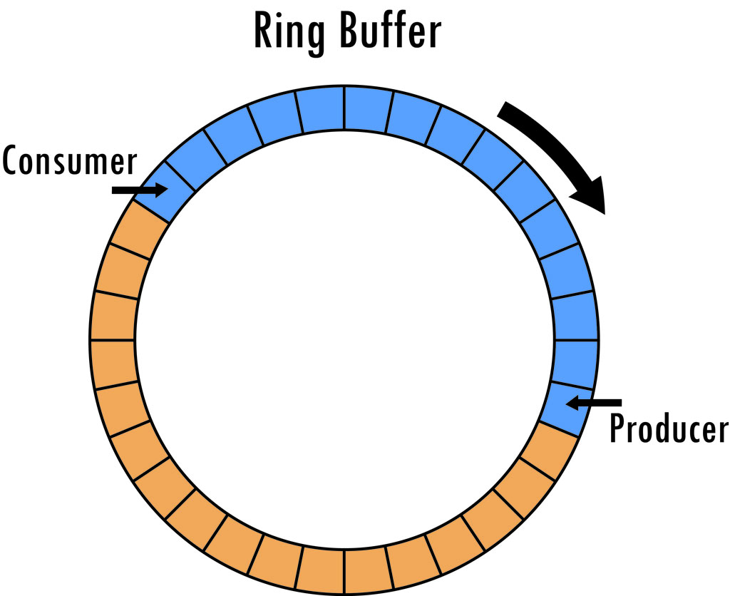
The canonical diagram of a ring buffer looks like so.
In this diagram, we have a buffer with 32 slots. The producer has filled 15 of them, indicated by blue. The consumer is behind the producer, reading data from the slots, freeing them as it does so. A free slot is indicated by orange.
Keep in mind that these sorts of diagrams are meant to demonstrate a concept and not so much depict an implementation. It’s certainly possible to implement a ring buffer that’s physically circular, as in the image above, using something like a linked list of separate smaller buffers. Quite often, however, you’ll see a ring buffer implemented using one big memory allocation. In this case, separate state is used to track used capacity as well as read and write indices.
Why Use a Ring Buffer?
You’ll most commonly see ring buffers used in circumstances that involve high volumes of data that need to be produced and consumed at high speeds. Real-time audio/video, network drivers, etc. are all contexts where you’ll find ring buffers being used. In these situations, performance of the data structure is key.
Performance takes a beating if you’re having to allocate and deallocate memory all the time. Memory allocation is slow. So ring buffers avoid it by allocating a chunk of memory one time and reusing it over and over. Memory fragmentation is also avoided.
Anything that involves locking (e.g., mutexes, and even memory allocation) is problematic when it comes to performance. You simply can’t predict how long a lock will be held. As we’ll see in our example implementation, ring buffers can be both thread-safe and lock-free.
Speed Is My Jam. When Would I Not Want to Use a Ring Buffer?
Ring buffers are ideally suited for the single producer/single consumer scenario. If there are more than one of either, things get complicated and locking will certainly need to be introduced either directly within the ring buffer or as a wrapper.
If you need your data structure to grow to an arbitrary size, then ring buffers are off the table.
If you need to explicitly control the lifetime of data within the ring buffer (e.g., if you need to hold pointers/references to contained data), then ring buffers are obviously the wrong choice.
If your data needs to be sorted or have a priority associated with it, ring buffers are the wrong choice here as well. Ring buffers are ALWAYS first-in, first-out.
The Gotcha
Because the ring buffer size is fixed, you sometimes have to experiment to find the optimum size to keep the producer ahead of the consumer at a rate that neither ever has to wait to do their job. Take the world of professional audio software as an example. Here, you’ll sometimes find the ring buffer capacity explicitly configurable within the UI as a mechanism for the user to tradeoff between audio latency and glitchy audio for a given hardware configuration.
Screenshot taken from Cakewalk BandLab
When is it ok for a producer to stomp over unconsumed data?
I mentioned earlier that in some scenarios it’s ok for a producer to stomp over unread data. When would this ever be ok? Consider a real-time audio or video streaming application such as a radio streamer or video conferencing app, or perhaps the broadcasting of player states in an online game. For sundry reasons, network hiccups occur. We’ve all experienced them. But regardless of the why, it’s always important to charge forward and have our applications processing the latest and greatest data.
Implementing an Audio Ring Buffer
The time has come. We’re going to implement a simple ring buffer in C++. We’ll make it data type agnostic and lock-free. Let’s start things off with a class skeleton, a constructor that allocates the buffer, and some state for tracking how much of the buffer is free.
This is a data type agnostic implementation. RingBuffer is a class template that allows clients to parameterize it with whatever data type they wish (so long as it’s memcpy and memcmp compatible).
The constructor allows the client to specify the size of the ring buffer. This is stored in m_capacity.
We also have a std::atomic<int> that’s used to track how many free slots are available for writing. Having this atomic is key to making this class thread-safe, as both producers and consumers will be indirectly checking this value during the reading and writing of ring buffer data.
You’ll also note that the constructor has a static_assert for ensuring that std::atomic<int> is lock free. This is to avoid any locking that could impact performance.
And just for fun, we initialize the contents of m_spBuffer to zero to put us in a known initial state. This isn’t really all that important. But it might benefit unit tests (which I did write for this, incidentally).
Next up, let’s add the state and functions needed for writing data into the buffer.
int m_writeIndex;// Initialized to zero in constructor. Not shown above.int getWriteableItemCount()const{return m_freeItems.load();}int write(DataType * pData, int numItems){int writeableItemCount = getWriteableItemCount();if(writeableItemCount ==0)return0;int totalItemsToWrite = std::min(writeableItemCount, numItems);// Note that writeableItemCount will do nothing to help us // determine if we're on the edge of the buffer and need to wrap around.// That's up to us to determine here.int itemsLeftToWrite = totalItemsToWrite;// Note that we're treating m_capacity like an index here for // one-past-the-end.if((m_writeIndex + itemsLeftToWrite)>= m_capacity){// We'd exceed the extent of the buffer here if wrote totalItemsToWrite samples, // so let's do a partial write.int itemsAvailableUntilEnd = m_capacity - m_writeIndex;memcpy(m_spBuffer.get()+ m_writeIndex, pData, itemsAvailableUntilEnd);// Bookkeeping
m_writeIndex =0;
itemsLeftToWrite -= itemsAvailableUntilEnd;
pData += itemsAvailableUntilEnd;}if(itemsLeftToWrite >0){memcpy(m_spBuffer.get()+ m_writeIndex, pData, itemsLeftToWrite *sizeof(DataType));// Bookkeeping
m_writeIndex += itemsLeftToWrite;
itemsLeftToWrite =0;}
m_freeItems -= totalItemsToWrite;return totalItemsToWrite;}
    int m_writeIndex; // Initialized to zero in constructor. Not shown above.

    int getWriteableItemCount() const
    {
        return m_freeItems.load();
    }

    int write(DataType * pData, int numItems)
    {
        int writeableItemCount = getWriteableItemCount();
        if (writeableItemCount == 0)
            return 0;

        int totalItemsToWrite = std::min(writeableItemCount, numItems);

        // Note that writeableItemCount will do nothing to help us
        // determine if we're on the edge of the buffer and need to wrap around.
        // That's up to us to determine here.
        int itemsLeftToWrite = totalItemsToWrite;

        // Note that we're treating m_capacity like an index here for
        // one-past-the-end.
        if ((m_writeIndex + itemsLeftToWrite) >= m_capacity)
        {
            // We'd exceed the extent of the buffer here if wrote totalItemsToWrite samples,
            // so let's do a partial write.
            int itemsAvailableUntilEnd = m_capacity - m_writeIndex;
            memcpy(m_spBuffer.get() + m_writeIndex, pData, itemsAvailableUntilEnd);

            // Bookkeeping
            m_writeIndex = 0;
            itemsLeftToWrite -= itemsAvailableUntilEnd;
            pData += itemsAvailableUntilEnd;
        }

        if (itemsLeftToWrite > 0)
        {
            memcpy(m_spBuffer.get() + m_writeIndex, pData, itemsLeftToWrite * sizeof(DataType));

            // Bookkeeping
            m_writeIndex += itemsLeftToWrite;
            itemsLeftToWrite = 0;
        }

        m_freeItems -= totalItemsToWrite;
        return totalItemsToWrite;
    }
There’s one new piece of state here and two new functions.
The new state, m_writeIndex, is used to track where the producer is writing next. This value is only ever used by the producer, so we don’t need to make it atomic.
The function getWriteableCount() merely returns the number of free slots available for writing in the ring buffer. It’s for the benefit of both the producer and the write() function itself.
The write() function attempts to write the specified number of items into the ring buffer and returns the actual number of items written. There are some things worth noting here.
We first check to see if we CAN actually write anything. If we can’t, we return immediately.
Next, we decide how MUCH we can actually write and store it in a local variable called totalItemsToWrite. This value may be less than what the producer requested if they requested more than we have space for. After that, we check to see if we might be trying to write more towards the end of the buffer than we have space for. If so, we write what we can and then loop back around to the beginning to write what’s left. Anything that’s left goes wherever the current write position is located.
Before leaving the function, we update the relevant member variables.
Now let’s look at the state and functions for reading data from the buffer.
int m_readIndex;// Initialized to zero in constructor. Not shown above.int getReadableItemCount()const{return m_capacity - m_freeItems.load();}int read(DataType * pData, int numItems){int readableItemCount = getReadableItemCount();if(readableItemCount ==0)return0;int totalItemsToRead = std::min(readableItemCount, numItems);// Note that readableItemCount will do nothing to help us // determine if we're on the edge of the buffer and need to wrap around.// That's up to us to determine here.int itemsLeftToRead = totalItemsToRead;if((m_readIndex + itemsLeftToRead)>= m_capacity){// We'd exceed the extent of the buffer here if read totalItemsToRead items, // so let's do a partial read.int itemsAvailableUntilEnd = m_capacity - m_readIndex;memcpy(pData, m_spBuffer.get()+ m_readIndex, itemsAvailableUntilEnd);// Bookkeeping
m_readIndex =0;
itemsLeftToRead -= itemsAvailableUntilEnd;
pData += itemsAvailableUntilEnd;}if(itemsLeftToRead >0){memcpy(pData, m_spBuffer.get()+ m_readIndex, itemsLeftToRead *sizeof(DataType));// Bookkeeping
m_readIndex += itemsLeftToRead;
itemsLeftToRead =0;}
m_freeItems += totalItemsToRead;return totalItemsToRead;}
    int m_readIndex; // Initialized to zero in constructor. Not shown above.

    int getReadableItemCount() const
    {
        return m_capacity - m_freeItems.load();
    }

    int read(DataType * pData, int numItems)
    {
        int readableItemCount = getReadableItemCount();
        if (readableItemCount == 0)
            return 0;

        int totalItemsToRead = std::min(readableItemCount, numItems);

        // Note that readableItemCount will do nothing to help us
        // determine if we're on the edge of the buffer and need to wrap around.
        // That's up to us to determine here.
        int itemsLeftToRead = totalItemsToRead;

        if ((m_readIndex + itemsLeftToRead) >= m_capacity)
        {
            // We'd exceed the extent of the buffer here if read totalItemsToRead items,
            // so let's do a partial read.
            int itemsAvailableUntilEnd = m_capacity - m_readIndex;
            memcpy(pData, m_spBuffer.get() + m_readIndex, itemsAvailableUntilEnd);

            // Bookkeeping
            m_readIndex = 0;
            itemsLeftToRead -= itemsAvailableUntilEnd;
            pData += itemsAvailableUntilEnd;
        }

        if (itemsLeftToRead > 0)
        {
            memcpy(pData, m_spBuffer.get() + m_readIndex, itemsLeftToRead * sizeof(DataType));

            // Bookkeeping
            m_readIndex += itemsLeftToRead;
            itemsLeftToRead = 0;
        }

        m_freeItems += totalItemsToRead;
        return totalItemsToRead;
    }
Much like the writing side of things, we have a new piece of state for tracking the consumer’s read position. We also have a complementary getReadItemCount() function for returning the number of items available for reading. And then there’s the read() function.
If you compare the write() and the read() function implementations here, you’ll see they’re almost exactly the same. There are only two big differences – the direction the data goes in and out of m_spBuffer and the way the member variables are updated (m_freeItems being incremented vs. decremented, and m_readIndex being used vs. m_writeIndex). Apart from that, they’re pretty much the same.
The checks against m_freeItems ensure that the consumer will never overtake the producer. And, in this implementation, the producer can never overwrite data. So accessing m_spBuffer from two different threads is safe because the producer and consumer are never accessing the same slots at the same time.
The only other shared state between the producer and the consumer is m_freeItems and that’s atomic.
The complete RingBuffer implementation is as follows.
/**
* A simple ring buffer class. This is thread-safe so long as only a
* single producer and a single consumer are clients.
*/template<typename DataType>class RingBuffer
{public:/**
* Constructor.
*
* @param capacity The total number of items to accommodate in the RingBuffer.
*/
RingBuffer(int capacity):
m_capacity(capacity),
m_freeItems(capacity),
m_readIndex(0),
m_writeIndex(0){// Lock-free would be important for scenarios that can't use locking, such// as real-time audio. If you don't have real-time concerns, then this can // possibly be removed.static_assert(ATOMIC_INT_LOCK_FREE ==2);
m_spBuffer = std::make_unique<DataType[]>(m_capacity);memset(m_spBuffer.get(), 0, sizeof(DataType)* m_capacity);}/**
* @return The number of items that can be read by the consumer.
*/int getReadableItemCount()const{return m_capacity - m_freeItems.load();}/**
* @return The number of items that can be written by the producer.
*/int getWriteableItemCount()const{return m_freeItems.load();}/**
* Attempts to read the specified number of items.
*
* @return The number of items read.
*/int read(DataType * pData, int numItems){int readableItemCount = getReadableItemCount();if(readableItemCount ==0)return0;int totalItemsToRead = std::min(readableItemCount, numItems);// Note that readableItemCount will do nothing to help us // determine if we're on the edge of the buffer and need to wrap around.// That's up to us to determine here.int itemsLeftToRead = totalItemsToRead;// Note that we're treating m_capacity like an index here for // one-past-the-end.if((m_readIndex + itemsLeftToRead)>= m_capacity){// We'd exceed the extent of the buffer here if we read totalItemsToRead // items, so let's do a partial read instead.int itemsAvailableUntilEnd = m_capacity - m_readIndex;memcpy(pData, m_spBuffer.get()+ m_readIndex, itemsAvailableUntilEnd);// Bookkeeping
m_readIndex =0;
itemsLeftToRead -= itemsAvailableUntilEnd;
pData += itemsAvailableUntilEnd;}if(itemsLeftToRead >0){memcpy(pData, m_spBuffer.get()+ m_readIndex, itemsLeftToRead *sizeof(DataType));// Bookkeeping
m_readIndex += itemsLeftToRead;
itemsLeftToRead =0;}
m_freeItems += totalItemsToRead;return totalItemsToRead;}/**
* Attempts to write the specified number of items. This is only
* guaranteed to write what we have space for. The amount of available
* space can be determined by invoking getWriteableItemCount().
*
* @return The number of items actually written.
*/int write(DataType * pData, int numItems){int writeableItemCount = getWriteableItemCount();if(writeableItemCount ==0)return0;int totalItemsToWrite = std::min(writeableItemCount, numItems);// Note that writeableItemCount will do nothing to help us // determine if we're on the edge of the buffer and need to wrap around.// That's up to us to determine here.int itemsLeftToWrite = totalItemsToWrite;// Note that we're treating m_capacity like an index here for // one-past-the-end.if((m_writeIndex + itemsLeftToWrite)>= m_capacity){// We'd exceed the extent of the buffer here if we wrote totalItemsToWrite// samples, so let's do a partial write instead.int itemsAvailableUntilEnd = m_capacity - m_writeIndex;memcpy(m_spBuffer.get()+ m_writeIndex, pData, itemsAvailableUntilEnd);// Bookkeeping
m_writeIndex =0;
itemsLeftToWrite -= itemsAvailableUntilEnd;
pData += itemsAvailableUntilEnd;}if(itemsLeftToWrite >0){memcpy(m_spBuffer.get()+ m_writeIndex, pData, itemsLeftToWrite *sizeof(DataType));// Bookkeeping
m_writeIndex += itemsLeftToWrite;
itemsLeftToWrite =0;}
m_freeItems -= totalItemsToWrite;return totalItemsToWrite;}private:
std::unique_ptr<DataType[]> m_spBuffer;//! The data.int m_writeIndex;//!< Where the producer is writing to next.int m_readIndex;//!< Where the consumer is reading from next.constint m_capacity;//!< Total number of frames managed by the ring buffer.
std::atomic<int> m_freeItems;//!< Number of frames that are available to be written into.};
/**
 * A simple ring buffer class. This is thread-safe so long as only a
 * single producer and a single consumer are clients.
 */
template<typename DataType>
class RingBuffer
{
public:
    /**
     * Constructor.
     *
     * @param capacity The total number of items to accommodate in the RingBuffer.
     */
    RingBuffer(int capacity) :
        m_capacity(capacity),
        m_freeItems(capacity),
        m_readIndex(0),
        m_writeIndex(0)
    {
        // Lock-free would be important for scenarios that can't use locking, such
        // as real-time audio. If you don't have real-time concerns, then this can
        // possibly be removed.
        static_assert(ATOMIC_INT_LOCK_FREE == 2);
        m_spBuffer = std::make_unique<DataType[]>(m_capacity);
        memset(m_spBuffer.get(), 0, sizeof(DataType) * m_capacity);
    }
    /**
     * @return The number of items that can be read by the consumer.
     */
    int getReadableItemCount() const
    {
        return m_capacity - m_freeItems.load();
    }
    /**
     * @return The number of items that can be written by the producer.
     */
    int getWriteableItemCount() const
    {
        return m_freeItems.load();
    }
    /**
     * Attempts to read the specified number of items.
     *
     * @return The number of items read.
     */
    int read(DataType * pData, int numItems)
    {
        int readableItemCount = getReadableItemCount();
        if (readableItemCount == 0)
            return 0;

        int totalItemsToRead = std::min(readableItemCount, numItems);
        // Note that readableItemCount will do nothing to help us
        // determine if we're on the edge of the buffer and need to wrap around.
        // That's up to us to determine here.
        int itemsLeftToRead = totalItemsToRead;
        // Note that we're treating m_capacity like an index here for
        // one-past-the-end.
        if ((m_readIndex + itemsLeftToRead) >= m_capacity)
        {
            // We'd exceed the extent of the buffer here if we read totalItemsToRead
            // items, so let's do a partial read instead.
            int itemsAvailableUntilEnd = m_capacity - m_readIndex;
            memcpy(pData, m_spBuffer.get() + m_readIndex, itemsAvailableUntilEnd);
            // Bookkeeping
            m_readIndex = 0;
            itemsLeftToRead -= itemsAvailableUntilEnd;
            pData += itemsAvailableUntilEnd;
        }
        if (itemsLeftToRead > 0)
        {
            memcpy(pData, m_spBuffer.get() + m_readIndex, itemsLeftToRead * sizeof(DataType));
            // Bookkeeping
            m_readIndex += itemsLeftToRead;
            itemsLeftToRead = 0;
        }
        m_freeItems += totalItemsToRead;
        return totalItemsToRead;
    }
    /**
     * Attempts to write the specified number of items. This is only
     * guaranteed to write what we have space for. The amount of available
     * space can be determined by invoking getWriteableItemCount().
     *
     * @return The number of items actually written.
     */
    int write(DataType * pData, int numItems)
    {
        int writeableItemCount = getWriteableItemCount();
        if (writeableItemCount == 0)
            return 0;
        int totalItemsToWrite = std::min(writeableItemCount, numItems);
        // Note that writeableItemCount will do nothing to help us
        // determine if we're on the edge of the buffer and need to wrap around.
        // That's up to us to determine here.
        int itemsLeftToWrite = totalItemsToWrite;
        // Note that we're treating m_capacity like an index here for
        // one-past-the-end.
        if ((m_writeIndex + itemsLeftToWrite) >= m_capacity)
        {
            // We'd exceed the extent of the buffer here if we wrote totalItemsToWrite
            // samples, so let's do a partial write instead.
            int itemsAvailableUntilEnd = m_capacity - m_writeIndex;
            memcpy(m_spBuffer.get() + m_writeIndex, pData, itemsAvailableUntilEnd);
            // Bookkeeping
            m_writeIndex = 0;
            itemsLeftToWrite -= itemsAvailableUntilEnd;
            pData += itemsAvailableUntilEnd;
        }
        if (itemsLeftToWrite > 0)
        {
            memcpy(m_spBuffer.get() + m_writeIndex, pData, itemsLeftToWrite * sizeof(DataType));
            // Bookkeeping
            m_writeIndex += itemsLeftToWrite;
            itemsLeftToWrite = 0;
        }
        m_freeItems -= totalItemsToWrite;
        return totalItemsToWrite;
    }
private:
    std::unique_ptr<DataType[]> m_spBuffer; //! The data.
    int m_writeIndex; //!< Where the producer is writing to next.
    int m_readIndex; //!< Where the consumer is reading from next.

    const int m_capacity; //!< Total number of frames managed by the ring buffer.
    std::atomic<int> m_freeItems; //!< Number of frames that are available to be written into.
};
Hopefully this article has helped you to appreciate the humble ring buffer a little bit more. If ring buffers were new to you before this article, I hope this was a helpful introduction and that you’ll be able to recognize them in the wild when you see them (they’re not always given helpful names like RingBuffer. 🙂 ). The implementation shown here is one of the simplest ones, and just one of many possible ways to do it.
If you find a bug in my code or have any questions or comments, please let me know. If you’ve seen any bizarre ring buffer implementations, tell me about that too. Weird code is always fun to see.
(Note: This is a slightly modified excerpt of Chapter 1 from a book I’ve been working on entitled “Digital Audio for C++ Programmers.”)
The decibel is perhaps one of the most confusing and misunderstood topics in audio. It has a confusing formula that appears to change based on the context. It’s also used in a variety of applications beyond audio. In fact, much of the documentation you’ll find is actually related electronics and telecommunications. And to muddy things even more, by itself the plain ole decibel doesn’t even really convey much meaning. It merely relates one power value to another. So, if after reading this article, you still find decibels confusing, don’t fret. You’re in good company.
The decibel originated with telephony in the early 1900’s. It was used as a way to describe the power efficiency of phone and telegraph transmission systems. It was formally defined as 1/10th of something called a bel. Interestingly, the bel was rarely used. The decibel got all the glory. The decibel has since found its way into all sorts of other domains, such as optics, electronics, digital imaging, and, most importantly to me, audio.
There are two benefits to using the decibel. The first is that switching to a logarithmic scale converts an awkward range of values (e.g., 0.0002 Pascals – 20 Pascals) to something much easier to reason about (e.g., 0 dB SPL – 120 dB SPL) . The other benefit applies to audio – a logarithmic scale is much closer to how the human ear actually hears. With a linear scale, like Pascals, doubling the value doesn’t usually feel like a doubling of loudness. With decibels, we actually get a scale that’s much closer to how to perceive loudness.
The decibel, in the generic sense, is not strictly a physical unit. When we think of physical units, we typically think about things like Amperes (number of moving electrons over time), Pascals (pressure), meters (distance), Celsius (temperature), etc. These are absolute units that correspond to physical things. The decibel isn’t like that. It’s a relative unit. It provides a relation of two things, which are themselves physical units. And it does this on a logarithmic scale.
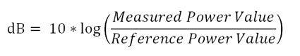
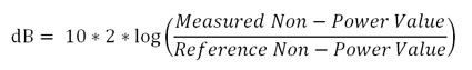
The general formula for the decibel is as follows.
The decibel, abbreviated dB, is the logarithmic ratio between two power values. One of these two values is a reference value. The other is a measured value.
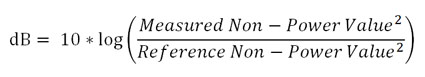
You may notice the phrase “power value” in that formula. In physics, this means the amount of energy transferred over time. The unit for power is usually the watt. However, there are plenty of units used that aren’t power values (such as Pascals in acoustic audio). So we have to convert those units into something related to power. This typically just means squaring the measured and reference values. The decibel formula ends up looking like so.
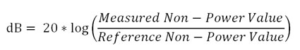
With logarithms, we can pull that exponent out and turn it into a multiplication.
This can be simplified even further like so.
And this is the formula you’ll most likely encounter when applying the decibel to measured and reference units which aren’t power-based (like Pascals in acoustic audio). It’s just a derivation of the original formula with the measured and reference values tweaked.
Standard Reference Values
A lot of domains, such as electronics and audio, have standardized reference values for the various things being measured. When we talk about these standardized flavors of the decibel, we add suffixes to the dB abbreviation. Examples of this are dBV (voltage based), dBm (radio power), dBZ (radar power), etc. The one we’re most concerned with in the field of acoustic audio is dB SPL.
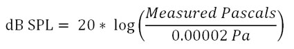
dB SPL
dB SPL is the most common flavor of decibel for indicating the loudness of acoustic audio. SPL stands for sound pressure level. The reference value used in calculating dB SPL is the threshold of human hearing – 0.000020 Pa. We plug this into the decibel formula along with a measured value, also in Pascals, to come up with a dB SPL value.
A measurement of 0 dB SPL is considered the threshold of human hearing. That is, it’s the quietest sound that the human ear is capable of hearing. On the upper end of the scale, somewhere between 130 dB SPL and 140 dB SPL, is what’s referred to as the threshold of pain. When the volume of sound approaches this level, it can result in physical discomfort and some amount of hearing loss is almost certain.
The following two tables shows some common sounds and their approximate sound pressure measurements. The first table shows measurements in Pascals. The second table shows them in dB SPL. Compare them and you’ll see that dB SPL is much less awkward to use.
Sound Source
Distance from Ear
Pascals
Jet Engine
1 meter
632
Threshold of Pain
At ear
20 – 200
Yelling Human Voice
1 inch
110
Instantaneous Hearing Loss Can Occur
At ear
20
Jet Engine
100 meters
6.32 – 200
Chainsaw
1 meter
6.32
Traffic on a Busy Road
10 meters
0.2 – 0.63
Hearing Loss from Prolonged Exposure
At ear
0.36
Typical Passenger Car
10 meters
0.02 – 0.2
Television (typical volume)
1 meter
0.02
Normal Conversation
1 meter
0.002 – 0.02
Calm Room
Ambient
0.0002 – 0.0006
Leaf rustling
Ambient
0.00006
Threshold of Hearing
At ear
0.00002
Sound Pressure Measured in Pascals, “Sound pressure” Wikipedia: The Free Encyclopedia. Wikimedia Foundation, Inc, 22 July 2004, https://en.wikipedia.org/w/index.php?title=Sound_pressure&oldid=1112496481. Accessed 29 Nov. 2022.
Sound Source
Distance from Ear
dB SPL
Jet Engine
1 meter
150
Threshold of Pain
At ear
130-140
Yelling Human Voice
1 inch
135
Instantaneous Hearing Loss Can Occur
At ear
120
Jet Engine
100 meters
110-140
Chainsaw
1 meter
110
Traffic on a Busy Road
10 meters
80-90
Hearing Loss from Prolonged Exposure
At ear
85
Typical Passenger Car
10 meters
60-80
Television (typical volume)
1 meter
60
Normal Conversation
1 meter
40-60
Calm Room
Ambient
20-30
Leaf rustling
Ambient
10
Threshold of Hearing
At ear
0
Sound Pressure Measured in dB SPL, “Sound pressure” Wikipedia: The Free Encyclopedia. Wikimedia Foundation, Inc, 22 July 2004, https://en.wikipedia.org/w/index.php?title=Sound_pressure&oldid=1112496481. Accessed 29 Nov. 2022.
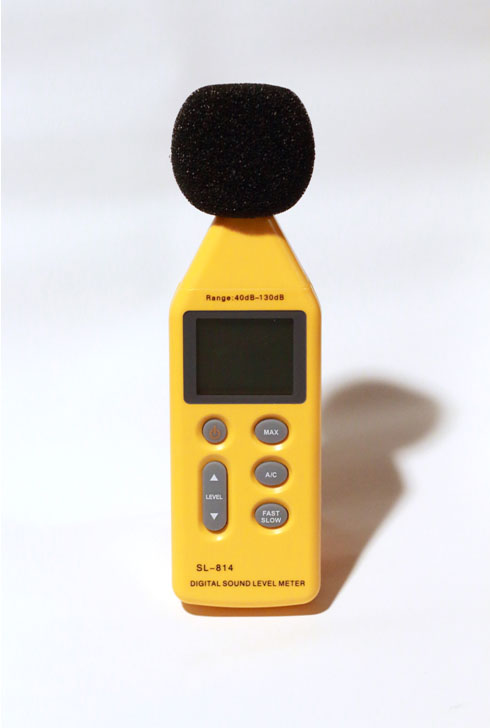
There are instruments available that measure sound pressure levels and report dB SPL. One such instrument is shown below. This happens to be my personal db SPL meter.
These devices are fun to take to concerts or demolition derbys if for no other reason than giving you the intellectual authority to complain about permanantly damaged hearing.
Conclusion
Hopefully, this article has helped demystify the decibel. Mathematically, they’re not something to be feared. It’s usually the logarithms that scare folks away. And if you’ve long since forgotten how logarithms work, go brush up on them and come back to this article a second time. It will make a lot more sense.
If you found this content useful, or if something could have been explained better, please leave me a comment below.