
In the previous article, I introduced my need to add sound capabilities to a radio-controlled robot project that I had been working on with my daughter. I focused on the DFPlayer as a potential solution and discussed how to control it using only an Arduino. However, I didn’t discuss radio control at all. Because the DFPlayer discussion was already pretty lengthy, I wanted to defer that discussion and write a separate article for that.
And here we are.
This time around, we’re going focus entirely on radio control. I’ll give a quick primer on how radio control and PWM works. We’ll also learn how to integrate radio control into an Arduino project. By the end, we’ll be ready to combine the concepts introduced in this article and the previous one to produce a radio-controlled audio player. We’ll save the final implementation for a third, and final, article.
Radio Controllers
A radio controller is typically a pair of devices – a radio transmitter and radio receiver. They cover the gamut in terms of cost and functionality. Whether you’re building a drone, an RC car, a robot, or a fun Halloween prop, there are a lot of radio solutions to choose from. For my purposes, I was just adding functionality to a pre-existing project using a radio that was already in use – the Flysky FS-i6x. That’s the radio controller I’ll be discussing here. But the concepts should carry over to pretty much any consumer-grade radio controller you buy off the shelf. I picked up the FS-i6x from Amazon for $59. (Although, at the time of this writing it appears the price has gone up slightly.)
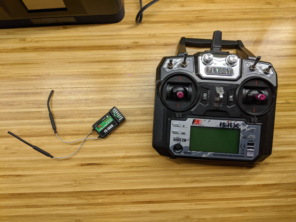
The Flysky FS-i6x is a 10-channel 2.4 GHz radio transmitter and comes with a 6-channel receiver that’s pre-bound to the radio. It supports tank-style channel mixing (after some configuration), a few common stick configurations, and a few extra switches and knobs that can be used for whatever you need.
Channels and Gigahertz, Oh My!
If you’re new to the radio controller world, you may be unfamiliar with the channels and frequency specifications that are used to characterize radio controllers.
The frequency number refers to the frequency band the radio transmitter uses to exchange information with the receiver. For newer RC systems, 2.4 GHz is commonplace. As far as the FCC is concerned, 2.4 GHz is part of the industrial, scientific, and medical unlicensed band. It’s a crowded band that’s shared by cordless phones, Bluetooth, WiFi, baby monitors, etc.
The number of channels a radio controller has refers to the number of separate “features” it supports. Each channel is tied to a separate control on the transmitter and has its own independent data associated with it. If you look at the picture of the transmitter above, you’ll see it has 2 sticks. Each of these sticks is associated with two channels – one for up and down and one for left and right. Each toggle switch is also a separate channel. And each knob is a separate channel too. (2 sticks x 2 channels per stick) + 4 toggle switches + 2 knobs = 10 channels. Other radio transmitters can have support for more channels and others can have less.
How Radio Controllers Work
Off the shelf, consumer-grade radio controllers are typically unidirectional as far as communication is concerned. Data flows from the radio transmitter to the radio receiver. There are some common exceptions to this rule. For instance, receiver-side battery strength and radio signal strength are often transmitted back to the transmitter for the user to monitor. But, in general, data is one way.
The way the data looks as it flows from transmitter to receiver will vary by manufacturer. There are no standards for consumer grade radio controllers that I’m aware of. If your receiver dies and needs replacing, or you simply want to buy another one so that you can use your transmitter in another project, you’ll need to find a receiver that’s compatible with your transmitter (usually from the same manufacturer).
On the receiver side, each channel will have a separate physical connector that can be used to connect to a servo, flight controller, general purpose microcontroller, Raspberry Pi, etc. The data that leaves these connectors is typically delivered as PWM signals.
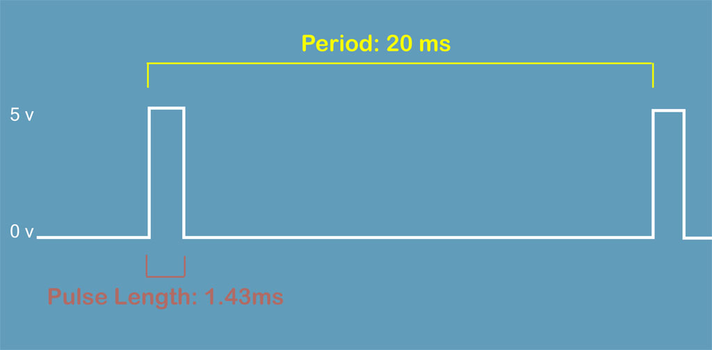
PWM
PWM stands for Pulse Width Modulation. The idea behind PWM is that we start with a low voltage and periodically pulse a higher voltage for a specific length of time. The length of this pulse is interpreted to mean something. What that something is depends entirely on your application and what you want it to mean.
I’ll show some code in a bit that allows us to see the range of PWM values emitted from the FS-i6x receiver.
Assigning Channels for the Sound Control
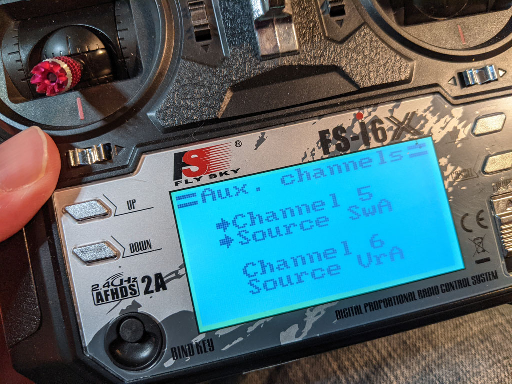
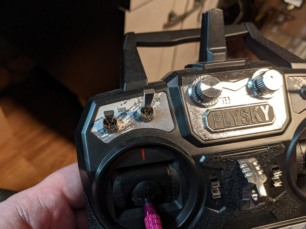
Channels 1-4 on my transmitter are reserved for the sticks, but channels 5 and 6 can be reassigned. I assigned channel 5 to the first toggle switch, which I’ll be using this to trigger audio playback. And I assigned the first knob to channel 6, which I’ll use to control volume.
On the receiver side, I just had to connect the signal pins for channels 5 and 6 to something that can read PWM. I connected the signal pins for these channels to the Arduino Nano’s pins 2 and 3, respectively. Pins 2 and 3 on the Nano can be especially useful here because they’re the only two pins on the Nano that support interrupts. At this point, I don’t actually need to use interrupts. I’m undecided if I’ll use them in the final project.
My connections looks like so.
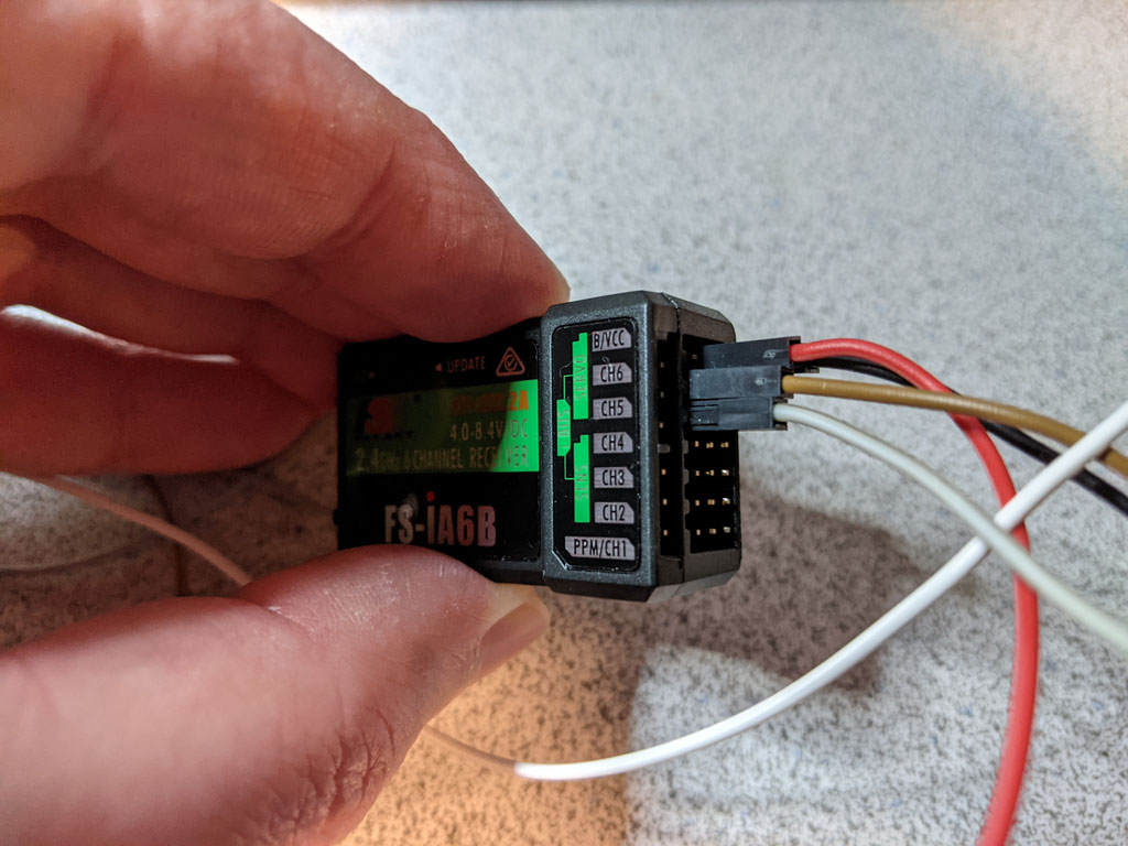

In addition to the channel connections, both the Arduino and the RC receiver are connected to a 5v power source. That’s what the red and black wires coming off both devices are for.
Now it’s time to see some code. For this test, I wanted to make sure that the Arduino is able to read data from the RC receiver, as well as find out the range of values delivered via PWM. The min and max range will be important to know in the final Arduino sketch for my project. My RC test sketch looks as follows.
void setup() { pinMode(2, INPUT); pinMode(3, INPUT); // For writing to the Serial Monitor on the PC. Serial.begin(9600); } void loop() { int audioTrigger = pulseIn(2, HIGH); int volumeKnob = pulseIn(3, HIGH); Serial.print("Trigger value: "); Serial.println(audioTrigger); Serial.print("Volume value: "); Serial.println(volumeKnob); delay(1000); } |
Short and sweet.
In the setup() function, I set the pin mode for pins 2 and 3 to INPUT and then set the baud rate for the serial port to 9600. The serial port is only important here for communication with the Arduino IDE’s Serial Monitor. It’s not needed for anything PWM related.
In the loop() function, I call pulseIn() for each pin. I pass HIGH so that pulseIn() measures the time the signal is high. I could have passed LOW in to measure the opposite, if it made sense to do so. This function returns the number of microseconds (not milliseconds) the pulse is in the specified state. After that, I simply send the values over the serial connection for display.
After uploading the sketch and powering everything up, both channels were initially reporting values in the vicinity of 1 ms (1000 microseconds).
Trigger value: 1002
Volume value: 994
When I toggled switch A on my radio, the trigger value jumped within the vicinity of 2 ms (2000 microseconds).
Trigger value: 1994
Since the trigger switch is either in position A or B, I can probably safely assume that any value less than 1.5ms is one value and any value equal to or higher than 1.5ms is the other.
When I turned the VRA knob on my radio, the volume values also began approaching a maximum value of 2 ms (2000 microseconds).
Volume value: 994
Volume value: 1326
Volume value: 1786
Volume value: 1998
Assuming the range is between 990 and 2000, I can map that to the range of values used to adjust the DFPlayer’s volume.
So now I have all the information I need to put together the final sketch, which we’ll do in the next article.