
The first time I touched an oscilloscope was in college. I was taking a second semester physics course. And while the course labs made pretty heavy use of oscilloscopes, I, like many of my classmates, learned just enough about them to get by. I’d walk through each lab assignment twisting dials and pushing buttons until I got something on the screen that resembled what I was supposed to see. And that was about it. Any amount of understanding that I actually had fell out of my brain once the semester was over.
As a software professional, the first time I encountered an oscope was while working for a very popular (at the time) mapping software company. The company was developing a new edition of its handheld GPS device and the LCD panel they had been using was officially end-of-lifed. Our hardware folks were having a hard time picking a replacement. It came down to two panels – one from Sharp and one from Epson. I was tasked with implementing a software driver for the Sharp, while someone else got the Epson up and running. For two solid days, I sat in my cube next to an oscope that I really, really hoped I wouldn’t need to use. I spent most of my time banging around on SPI code and reading documentation. However, I’d occasionally hit a wall. That meant putting on my best sad puppy dog face and shuffling as pathetically as I could into one of the hardware guys’ offices to ask for some oscope help. In the end, I managed to get the driver working. But the experience wasn’t great and it bruised my ego somewhat. (As a bonus kick-in-the-fruitbasket, the company opted for the Epson panel.)
I really wish I could say that was an isolated incident. But the truth is that story has more or less repeated itself a few times throughout my career. The companies, colleagues, and products have changed, but the need to use an oscope continues to pop up.
A few months ago, I was watching an old episode of “Know How”. The episode was primarily about a cheap DIY entry-level oscilloscope kit from JYE Tech – the DSO 138. It looked super simple and a lot of fun to play with. There were no built in function generators and no fancy math functions. There were just a few buttons and switches to learn. It also appeared easy to assemble.
As I watched the episode, I relived each of my horrible oscope encounters. I felt slightly embarrassed to have come this far in my career without having some level of comfort with oscopes – even the DSO 138 intimidated me on some level. So I pulled the trigger and bought the kit.
About The DSO 138
As I mentioned above, the DSO 138 is an entry-level, DIY oscilloscope kit from JYE. Let me bold and italicize that phrase one more time – entry-level. It can only handle signals up to 200 KHz. It samples at a maximum rate of 1 million samples per second. And it’s limited to a maximum peak input voltage of 50 V. If your primary use case is audio applications or testing PWM signals, this kit should be just fine for you.
 The kit arrives as a bare PCB board along with a 2.4” LCD, a bag of assorted components, test leads, and some assembly instructions. This being a kit, of course, means that you have to solder everything up. And depending on which flavor of the DSO 138 you get, you may or may not have to solder a few surface mount components as well. I’ll have more to say about this in a minute.
The scope is built around the STM32F103C8, which is an ARM-based microcontroller from ST. The STM32F103C8 has a 72MHz CPU, 2 12-bit ADCs (12-bits is the max resolution of the oscope, incidentally), 20KB of SRAM, and 64KB or 128KB of Flash (not sure which version was selected for this kit). It also comes pre-flashed with firmware for this project, so you don’t have to worry about doing it yourself.
The board features two options for power – a traditional barrel connector and a JST connector. There are 3 slide switches – one is for controlling in the input type and the other two are used to select range and sensitivity. Four buttons are used to control various on-screen parameters. A fifth button provides a reset. There’s also a USB connector included in the mix. It’s curious, however, because the USB connector doesn’t actually seem to have a purpose. It’s optional to install and the accompanying documentation says, “It was provided for future or user own use.” I haven’t been brave enough to see if I can power the board from it.
The board also features a built-in 1KHz 3.3V test signal, which you can use to verify that things are working as they should.
Purchasing the DSO 138
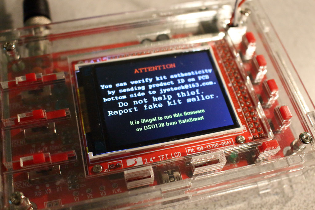 You can obtain the DSO 138 from a number of online retailers such as Amazon, Banggood, Ebay, etc. When purchasing the DSO 138, you should probably make sure you buy it from an approved seller. There are a number of counterfeit kits floating around. And JYE doesn’t mince words when it comes to them. They call out sellers by name both on their website and in their firmware splash screen. I purchased mine from an Amazon seller name NooElec, which is apparently on the “approved” list.
For reasons I describe below, I ended up buying two kits at two different times using the same Amazon link. And I got two different flavors of the DSO 138 – the 13803K and the 13804K. The only difference between these two versions are the surface mount components. The 13803K comes with all of the surface mount components presoldered. The 13804K has the ST chip presoldered and nothing else, which means you’ve got more soldering to do.
I thought I had bought the 13803K the first time, but the 13804K showed up on my doorstep. Unless the idea of soldering surface mount resistors strikes fear into your soul, it’s not that big of a deal. Incidentally, this was my first time with SMDs and I had no problem at all.
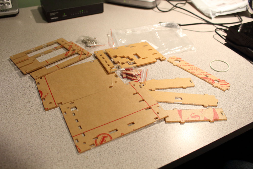 Something to keep in mind with this kit as well is that it doesn’t come with a case. If you intend to use the DSO 138 on a semiregular basis, you might want to consider purchasing a case. (This is especially true if you use leaded solder when putting it together. :-)) A company named Smartcoco makes cheap clear acrylic cases for the DSO 138 which can be found on Amazon. Unfortunately, it doesn’t come with instructions, so you’ll need to turn to YouTube for help
Assembly
The DSO 138 assembly process is fairly straightforward. The directions are actually quite good. As in all electronics projects, you should always start out soldering the components with the lowest profiles and then work your way up to the taller, beefier components. It took me approximately three hours to finish soldering the main board (which includes a pee break and at least 2 soda refills).
If you do end up getting the 13804K and you’ve never soldered an SMD before, don’t panic. As I said before, I had never soldered SMD prior to this either. If my fat fingers and shaky hands can do it, so can yours. There are plenty of YouTube videos that provide tips and tricks for this. Just watch a couple of them prior to getting started and you’ll be just fine.
One minor annoyance about this project is that the through-hole resistors are blue (at least they were in my kit). The blue color totally messed with my ability to discern the colors of the resistor’s bands. I had to measure each resistor one by one to figure out what was what. There are only 23 resistors included, so it wasn’t terribly painful. And I suppose you should always measure these things anyway as a way of double-checking. “Measure twice, solder once,” as they say.
I did make the horrible mistake of doing some soldering while tired and feeling rushed. As a result, I soldered the pin connector to the wrong side of the LCD board. Whoops! This, of course, meant that I wasted a LOT of time trying to desolder it without destroying the solder pads or the pin connector…both of which I did anyway.
If, like me, you do screw up the LCD pin connector, you can find a replacement at AccuDIY. However, you’ll probably pay more than you should in getting it. The LCD is listed at $7.60 at the time of this writing. Shipping on that item was over $10 for me – way too steep for such a part. It actually made more sense for me to purchase an entire second DSO 138 kit in case I screwed something else up too (which I didn’t, thankfully. ;-)).
After I finished assembling everything, I did a quick test with the built in 1KHz 3.3 V test signal. That checked out ok. I then did a lengthier test using my favorite signal generator – my Sansa MP3 player. I fired up a Foo Fighters tune and watched the display dance around for a while.
Conclusion
I’ve still got some work to do in learning the DSO 138. When purchasing this kit, I also picked up a cheap high frequency signal generator kit. At the time of this writing, I haven’t assembled it yet. But once I do, I’ll probably write a short article about it as well.
What do I think about the DSO 138 thus far? It’s definitely worth the $25. Assembly was fun and gratifying. For low frequency signal sources, it seems to be fairly accurate. And the electrical noise level is surprisingly low. I definitely recommend it to everybody. Even electronics gurus will find one of these handy to keep in the toolbox (it’s portable!).
But as LeVar Burton says, “You don’t have to take my word for it”. Check out the DSO 138 review done by GreatScott!