2025/Nov/17 – Correction: It’s been pointed out that my use use of the word “looper” in this article isn’t accurate. The type of pedal I build here is colloquially referred to as a “loop switcher.”
 For guitar players, the word “looper” usually calls to mind one of two types of effects pedals – audio samplers and signal path modifiers.
Sampler/repeating loopers record whatever the guitarist is doing for some period of time and then they loop the recording until the guitarist makes it stop. Think Loop Station from BOSS or the DITTO Looper from TC Electronic. Guitarists typically use these types of pedals to create backing tracks to play against. And while they have a reputation for being difficult to work with in a live setting or when playing with other musicians, they’re great brainstorming tools.
Loopers of the signal path variety allow the guitarist to control chains of effects. Think of an effect loop on an amp. An amp’s effects loop allows you to chain a bunch of effects together and apply them to the guitar signal after the preamp gets a chance to do its work, but before the power is applied to the signal. This prevents the preamp from noising up your effects. It also has the added advantage of allowing you, the guitarist, to bypass the effects loop altogether with the push of a single button. A pedal-based looper on its own doesn’t help you much in the post preamp department, but it does enable you to cluster effects and toggle the cluster on/off with a single footswitch press. You’re also not limited to a single pedal-based effects loop. You can have as many as you want. And because the loops themselves can be chained together, a guitarist has enormous flexibility in how they control the effects applied to their signal.
This blog entry will be concerned only with the latter type of pedal. When I say looper, I’m speaking entirely of the signal routing variety.
Motivation
I’ve got somewhere in the neighborhood of three dozen effects pedals (maybe more) in my “Box O’ Sounds”. Do I use them all? No. Certainly no more than half a dozen ever leave my practice space. But there are a number of pedals that I almost always use together to achieve a particular sound. And it’s important to me to be able to toggle them on/off together. Unless I’m super fast and feeling really coordinated, this can be really awkward. This is especially true in a live scenario where the mind can wander. Being able to treat a few pedals as a single unit is ideal. And that’s what motivated me to start exploring loopers. Once I realized how simple they were to build, I couldn’t resist trying to build one for myself.
As far as guitar pedals go, loopers are probably the easiest of all pedals to build because they don’t really modify the signal. A looper just routes the signal to different locations using a bunch of wire, switches, and jacks. They’re easy to understand. There’s almost never a circuit board mounted inside one of these things (unless you’re looking at a digital, MIDI-control unit like those from RJM Music Technology).
Materials
The following is a list of parts I used to build my looper. This listing is for four channels. If you don’t need that many channels, adjust accordingly.
- Enclosure – I went with a 4S1032L aluminum enclosure from 4Site Electronics.
- 24AWG single strand wire. Color really isn’t important. But I picked up some violet, red, and black spools just to help eyeball where things are going.
- 4 3PDT footswitches (one for each loop).
- 1 ¼” stereo jack (used on the instrument side of the pedal).
- 9 ¼” mono jacks (1 for the amp side of the pedal and then 2 for each loop).
- 4 5mm LEDs (I went with blue).
- 4 LED bezels (I used to some cheap plastic LED mounting clips from Mouser)
- 4 10KOhm resistors (1 for each LED)
- Optional Power jack – 2.1mm is the conventional power jack size. I went with a 3 pin, panel mount barrel connector.
- 9V battery connector.
Schematic
I looked around at various schematics online and ultimately created one tailored to my own needs. Below is a completely unoriginal schematic I drew based on other designs from numerous other people.

Some things worth noting:
No power is actually needed for the looper to function. Power is only really needed for the LEDs. If the battery dies or you unplug the looper from external power, you’ll still be able to use the effects loops. You’ll just have to rely on your ears to know what state the looper is in. The less I have to think about this stuff, the more I can focus on the songs. So, for me, it’s important that the LEDs work.
If you think about the switch, loop jacks, LED, and resistor as a discrete unit, you’ll realize these things are just blocks of components chained together. You can easily add or remove clusters of these to get just the right number of loops for your taste.
Pedal Design
 The first thing I did after getting all of my parts was to design the internal layout of the pedal. It’s important that you take some time to plan this stuff out. There are a lot of bulky components going into this pedal. It’s easy to assume you’ve got plenty of room to work with. Looks can be deceiving. I can’t stress this enough – PLAN THE LAYOUT. Enclosures aren’t cheap. And ruining a build because you’re overconfident with the drill can be really discouraging.
I did all of my planning in 3DSMax just because that’s what I know how to use. I couldn’t find a source for good 3D models of my components, so I ended up modeling them myself. I didn’t get incredibly detailed with them. I just made sure the overall dimensions were accounted for.
Enclosure Prepping
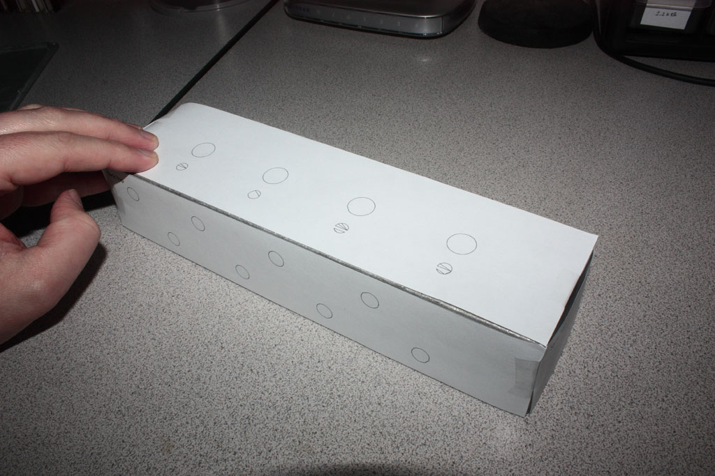 After putting together a 3D model of my parts, enclosure, and drill holes, I exported vector artwork of the various sides and brought them into Adobe Illustrator. From Illustrator, I was able to print the artwork out to scale. This became my drilling template. I cut out each side and taped them to the enclosure.
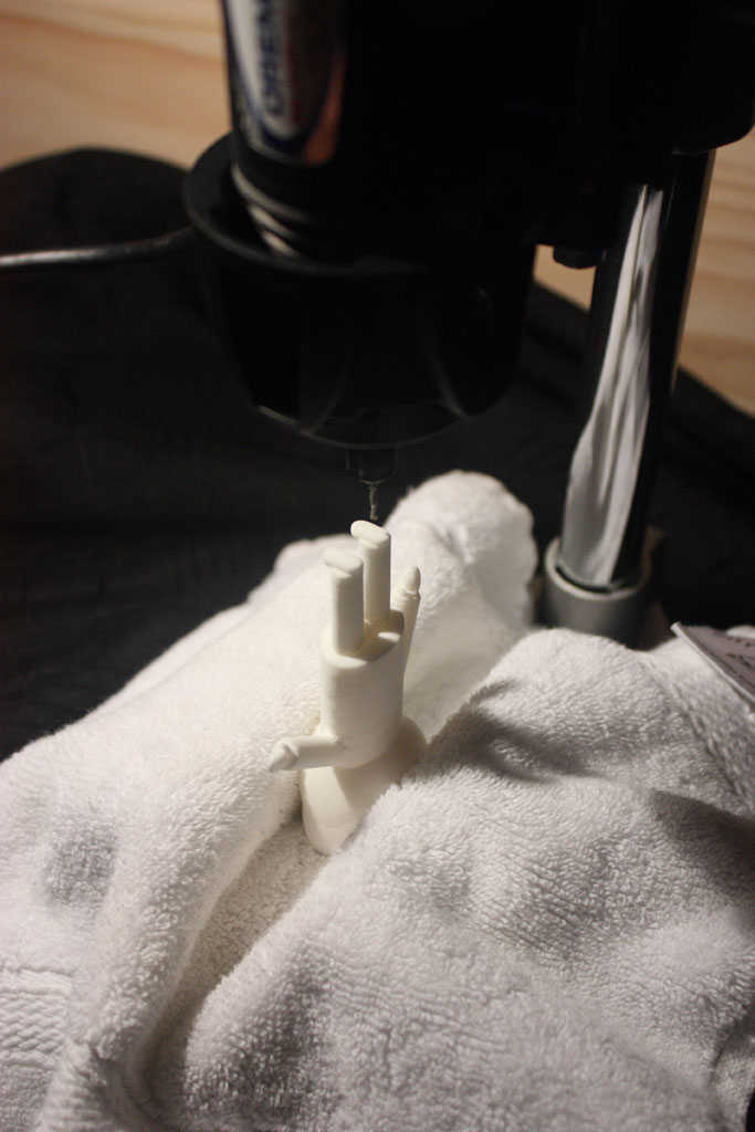
I drilled a few small pilot holes to get started and then switched to a stepped drill bit to get the right size holes that I needed. I recommend double checking the hole sizes against the components as you go just to make sure the holes aren’t too big. It’s easier to make a hole bigger. But there’s not much you can do about a hole that’s too big. A little wiggle room is ok for a jack or a switch. But too much and you’ll need to start over with a new enclosure or buy bigger washers.
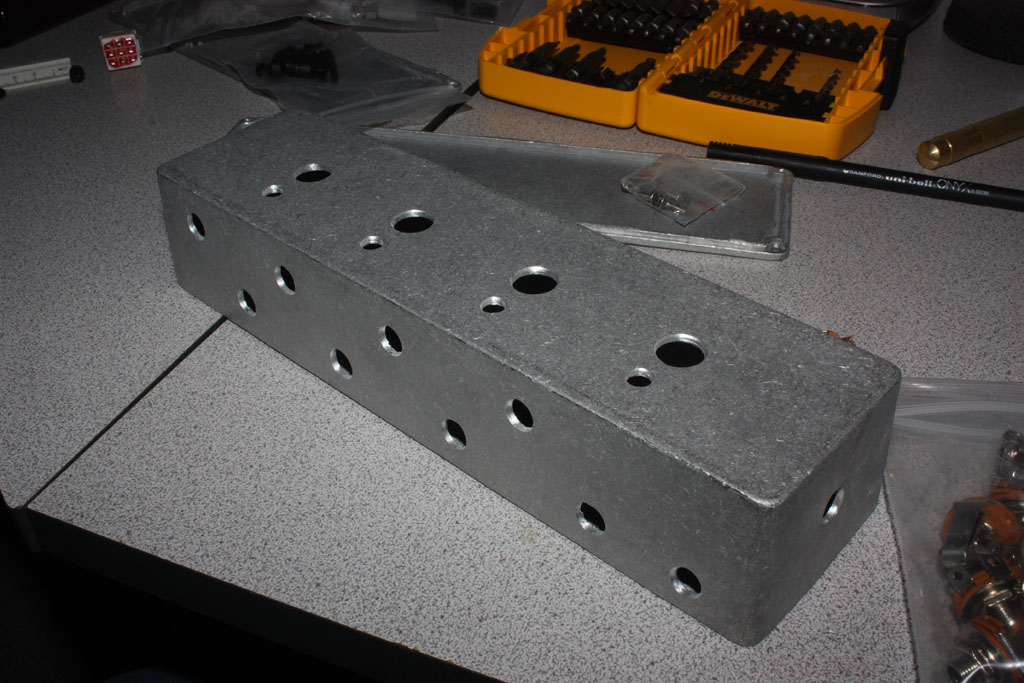 With the holes drilled, you might think about sanding and/or painting the enclosure. I wasn’t too thrilled with the factory finish on the enclosures. I wanted more of a brushed look, so I sanded everything down.
I started with 80 grit sandpaper, graduated to 100 grit, and then finished with 150 grit. Since I wanted to have a brushed finish, it was important that I paid attention to the direction I sanded. If you don’t sand in a single direction, it won’t look brushed at all. I finished up with some super fine steel wool. And then cleaned everything off with some mineral spirits. After the mineral spirits evaporated, I rinsed everything off.
Wiring Up
This may seem like an obvious thing to say, but I know someone will make the mistake so I’ll say it anyway. Make sure you do you wiring and soldering OUTSIDE of the enclosure. You can periodically test fit components to make sure your runs of wire are the right length. But you’ll cause yourself major headaches if you try to solder things inside the enclosure.
Something I did that may come back to bite me is wiring my instrument-in and amp-out jacks on ends opposite to the switches they’re connected to. It was important for me to follow the convention of having the instrument-in on the right side and the amp-out on the left side of the enclosure. It was also important for me to think about the loop channels as running from left to right. So in order to accomplish that, I ended up having to add an extra 16+ inches or so of wire that I wouldn’t otherwise need if I were willing to compromise. The extra wire creates an opportunity for more noise and signal degradation. But it’s not something I’ve really noticed as of yet. If it does come back to haunt me, I’ll probably end up rewiring this thing at some point.
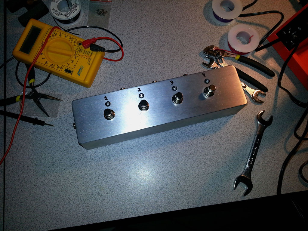
Regarding the LEDS, this was the first time I had ever used plastic holders. The idea is you snap the holder into the hole and then pop the LED in from the bottom. The problem is the LED isn’t held very tightly and it’ll pop out as easily as it popped in. I’m not sure how most folks deal with this, but I put a little dab of super glue around both the outside of the holder (prior to insertion) and on the outer edge of the LED (wipe off any excess that shows up on the top of the enclosure). That seemed to work ok. But time will tell how well it holds up.
Conclusion
There’s not much to this project. Troubleshooting should be fairly straightforward. As you build, test for continuity along the way. Even the cheapest of multimeters can do this and it’ll save you loads of trouble.
For those new to pedal building, there are some fantastic resources online to help guide you along. Some of my favorites are below:
Planet Z – This is a website run by a wonderful fellow named John Cooper. He has SUPERB introductory video tutorials on enclosure and pedal design. He goes into much more detail than I did. He also has a fantastic tutorial on Sketchup. If you’re new to 3D modeling and are looking for a low-cost (free) way to take your first steps, Sketchup is the way to go.
gaussmarkov: diy fx – You’ll find loads of great material here on components and effects-related circuits. Gaussmarkov even took the time to create beautiful POVRAY renderings to help illustrate some of the material. I think the most valuable section here for first time builders is the Parts section.
ProGuitarShop.com – FX Loops Explained – This isn’t really a builder site. But it contains a great high-level discussion of effects loops. If you’re new to the idea of effects loops, or have always wondered what was so special about your amp’s effects loop, check out this article.
Good luck!
-Shane