DIY Guitar Fx: 4 Channel Audio Looper

For guitar players, the word “looper” usually calls to mind one of two types of effects pedals – audio samplers and signal path modifiers.

Sampler/repeating loopers record whatever the guitarist is doing for some period of time and then they loop the recording until the guitarist makes it stop. Think Loop Station from BOSS or the DITTO Looper from TC Electronic. Guitarists typically use these types of pedals to create backing tracks to play against. And while they have a reputation for being difficult to work with in a live setting or when playing with other musicians, they’re great brainstorming tools.

Loopers of the signal path variety allow the guitarist to control chains of effects. Think of an effect loop on an amp. An amp’s effects loop allows you to chain a bunch of effects together and apply them to the guitar signal after the preamp gets a chance to do its work, but before the power is applied to the signal. This prevents the preamp from noising up your effects. It also has the added advantage of allowing you, the guitarist, to bypass the effects loop altogether with the push of a single button. A pedal-based looper on its own doesn’t help you much in the post preamp department, but it does enable you to cluster effects and toggle the cluster on/off with a single footswitch press. You’re also not limited to a single pedal-based effects loop. You can have as many as you want. And because the loops themselves can be chained together, a guitarist has enormous flexibility in how they control the effects applied to their signal.

This blog entry will be concerned only with the latter type of pedal. When I say looper, I’m speaking entirely of the signal routing variety.

Motivation

I’ve got somewhere in the neighborhood of three dozen effects pedals (maybe more) in my “Box O’ Sounds”. Do I use them all? No. Certainly no more than half a dozen ever leave my practice space. But there are a number of pedals that I almost always use together to achieve a particular sound. And it’s important to me to be able to toggle them on/off together. Unless I’m super fast and feeling really coordinated, this can be really awkward. This is especially true in a live scenario where the mind can wander. Being able to treat a few pedals as a single unit is ideal. And that’s what motivated me to start exploring loopers. Once I realized how simple they were to build, I couldn’t resist trying to build one for myself.

As far as guitar pedals go, loopers are probably the easiest of all pedals to build because they don’t really modify the signal. A looper just routes the signal to different locations using a bunch of wire, switches, and jacks. They’re easy to understand. There’s almost never a circuit board mounted inside one of these things (unless you’re looking at a digital, MIDI-control unit like those from RJM Music Technology).

Materials

The following is a list of parts I used to build my looper. This listing is for four channels. If you don’t need that many channels, adjust accordingly.

  • Enclosure – I went with a 4S1032L aluminum enclosure from 4Site Electronics.
  • 24AWG single strand wire. Color really isn’t important. But I picked up some violet, red, and black spools just to help eyeball where things are going.
  • 4 3PDT footswitches (one for each loop).
  • 1 ¼” stereo jack (used on the instrument side of the pedal).
  • 9 ¼” mono jacks (1 for the amp side of the pedal and then 2 for each loop).
  • 4 5mm LEDs (I went with blue).
  • 4 LED bezels (I used to some cheap plastic LED mounting clips from Mouser)
  • 4 10KOhm resistors (1 for each LED)
  • Optional Power jack – 2.1mm is the conventional power jack size. I went with a 3 pin, panel mount barrel connector.
  • 9V battery connector.

Schematic

I looked around at various schematics online and ultimately created one tailored to my own needs. Below is a completely unoriginal schematic I drew based on other designs from numerous other people.

Some things worth noting:

No power is actually needed for the looper to function. Power is only really needed for the LEDs. If the battery dies or you unplug the looper from external power, you’ll still be able to use the effects loops. You’ll just have to rely on your ears to know what state the looper is in. The less I have to think about this stuff, the more I can focus on the songs. So, for me, it’s important that the LEDs work.

If you think about the switch, loop jacks, LED, and resistor as a discrete unit, you’ll realize these things are just blocks of components chained together. You can easily add or remove clusters of these to get just the right number of loops for your taste.

Pedal Design

The first thing I did after getting all of my parts was to design the internal layout of the pedal. It’s important that you take some time to plan this stuff out. There are a lot of bulky components going into this pedal. It’s easy to assume you’ve got plenty of room to work with. Looks can be deceiving. I can’t stress this enough – PLAN THE LAYOUT. Enclosures aren’t cheap. And ruining a build because you’re overconfident with the drill can be really discouraging.

I did all of my planning in 3DSMax just because that’s what I know how to use. I couldn’t find a source for good 3D models of my components, so I ended up modeling them myself. I didn’t get incredibly detailed with them. I just made sure the overall dimensions were accounted for.

Enclosure Prepping

After putting together a 3D model of my parts, enclosure, and drill holes, I exported vector artwork of the various sides and brought them into Adobe Illustrator. From Illustrator, I was able to print the artwork out to scale. This became my drilling template. I cut out each side and taped them to the enclosure.

I drilled a few small pilot holes to get started and then switched to a stepped drill bit to get the right size holes that I needed. I recommend double checking the hole sizes against the components as you go just to make sure the holes aren’t too big. It’s easier to make a hole bigger. But there’s not much you can do about a hole that’s too big. A little wiggle room is ok for a jack or a switch. But too much and you’ll need to start over with a new enclosure or buy bigger washers.

With the holes drilled, you might think about sanding and/or painting the enclosure. I wasn’t too thrilled with the factory finish on the enclosures. I wanted more of a brushed look, so I sanded everything down.

I started with 80 grit sandpaper, graduated to 100 grit, and then finished with 150 grit. Since I wanted to have a brushed finish, it was important that I paid attention to the direction I sanded. If you don’t sand in a single direction, it won’t look brushed at all. I finished up with some super fine steel wool. And then cleaned everything off with some mineral spirits. After the mineral spirits evaporated, I rinsed everything off.

Wiring Up

This may seem like an obvious thing to say, but I know someone will make the mistake so I’ll say it anyway. Make sure you do you wiring and soldering OUTSIDE of the enclosure. You can periodically test fit components to make sure your runs of wire are the right length. But you’ll cause yourself major headaches if you try to solder things inside the enclosure.

Something I did that may come back to bite me is wiring my instrument-in and amp-out jacks on ends opposite to the switches they’re connected to. It was important for me to follow the convention of having the instrument-in on the right side and the amp-out on the left side of the enclosure. It was also important for me to think about the loop channels as running from left to right. So in order to accomplish that, I ended up having to add an extra 16+ inches or so of wire that I wouldn’t otherwise need if I were willing to compromise. The extra wire creates an opportunity for more noise and signal degradation. But it’s not something I’ve really noticed as of yet. If it does come back to haunt me, I’ll probably end up rewiring this thing at some point.

Regarding the LEDS, this was the first time I had ever used plastic holders. The idea is you snap the holder into the hole and then pop the LED in from the bottom. The problem is the LED isn’t held very tightly and it’ll pop out as easily as it popped in. I’m not sure how most folks deal with this, but I put a little dab of super glue around both the outside of the holder (prior to insertion) and on the outer edge of the LED (wipe off any excess that shows up on the top of the enclosure). That seemed to work ok. But time will tell how well it holds up.

Conclusion

There’s not much to this project. Troubleshooting should be fairly straightforward. As you build, test for continuity along the way. Even the cheapest of multimeters can do this and it’ll save you loads of trouble.

For those new to pedal building, there are some fantastic resources online to help guide you along. Some of my favorites are below:

Planet Z – This is a website run by a wonderful fellow named John Cooper. He has SUPERB introductory video tutorials on enclosure and pedal design. He goes into much more detail than I did. He also has a fantastic tutorial on Sketchup. If you’re new to 3D modeling and are looking for a low-cost (free) way to take your first steps, Sketchup is the way to go.

gaussmarkov: diy fx – You’ll find loads of great material here on components and effects-related circuits. Gaussmarkov even took the time to create beautiful POVRAY renderings to help illustrate some of the material. I think the most valuable section here for first time builders is the Parts section.

ProGuitarShop.com – FX Loops Explained – This isn’t really a builder site. But it contains a great high-level discussion of effects loops. If you’re new to the idea of effects loops, or have always wondered what was so special about your amp’s effects loop, check out this article.

Good luck!

-Shane

Adventures in 3D Printing: From Concept to Cake Topper


The Invitations

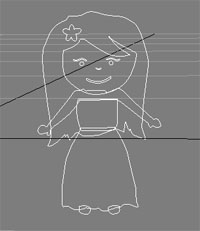
When Leora and I decided to design our own wedding invitations, I had no idea how far we’d go with it. Cake toppers weren’t even on our radar at the time. Our attitude was that we’d try to design our own invitations and if it turned out like crap, we’d find something nice online to use. We knew we wanted to create something fun that also represented who we are. But that was about it. We didn’t really have anything more specific in mind. Leora, the artistic one of us, decided to go off on her own and brainstorm. After returning from band practice one evening, I found these sketches sitting on our coffee table.


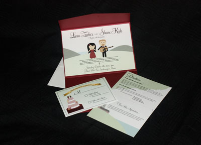
It was my task to take these drawings and turn them into something resembling wedding invitations. So I photographed them and brought them into Photoshop. I fired up the trusted pen tool and traced each body part onto a separate layer. After some coloring and some recompositing, I ended up with the image you see on the right.

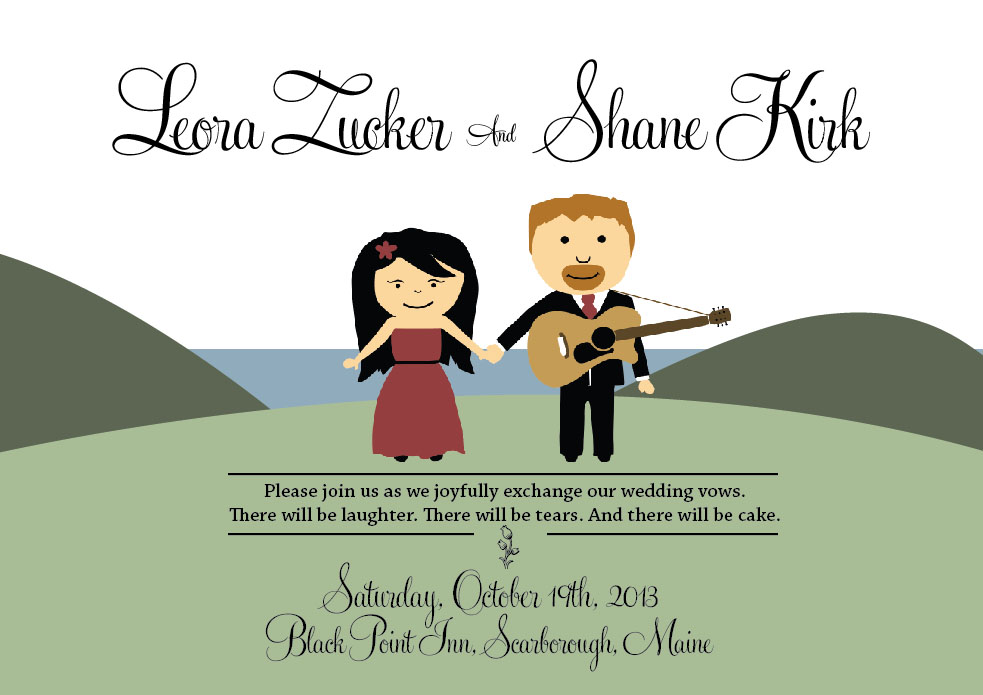
Printed text always looks better when it’s sourced from vector artwork. So I did the rest of the invitation layout within Illustrator. I imported the raster from Photoshop and began experimenting with different designs. After a few days of messing about, Leora and I both settled on the following design.

I then did a test print on my laser printer. The results were horrible. All of the Illustrator-drawn content looked wonderful, but the raster had an ugly discolored box poking through the areas that should have been transparent. I tried importing the raster as a transparent PNG, as well as importing the Photoshop file directly. I experimented with color settings, printer settings, document settings, PDF export settings, etc. And the results just went from bad to worse.

I realized I needed to start over…kind of. The raster image had to go. I needed to redo the artwork in a vector format within Illustrator. But the idea of retracing the drawings was a bit daunting. Fortunately, Illustrator has a tool that automates tracing.

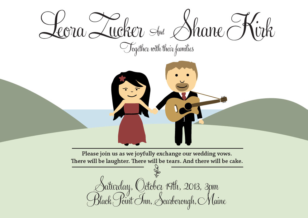
Layer by layer, I exported everything from my original Photoshop file as a separate two-color image (black foreground, white background) and then let Illustrator trace it all. Once each element had been vectorized, I restored its original color. The test prints also proved to us that our colors were too strong. After all was said and done, we ended up with the following, which was much, much better.

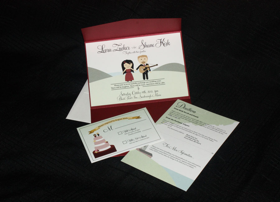
Now the test prints looked great. And because we were using vectors, it was much easier to reuse the artwork on our RSVP cards.

Wedding Favors

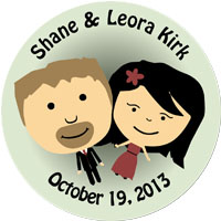
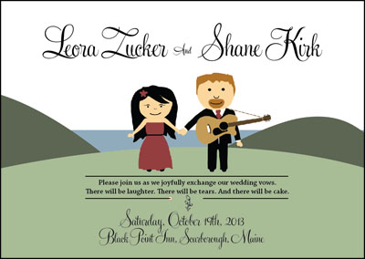
Next up – wedding favors! We struggled a bit with this. I really wanted 3D ViewFinders with custom reels. I was told it was too expensive, too ambitious. I also suggested miniature figurines of the artwork Leora drew for our invites. Again, too expensive, too ambitious. (See a pattern here?) Leora and her sister, Tal, had their own ideas – mugs, stickers, and a candy bar (as in a candy buffet). But because we didn’t have a large budget for favors, Leora decided that simpler was better – a small pouch with Maine candies and a custom magnet. Leora really liked the idea of reusing our invitation artwork. And because the artwork ended up being entirely vector-based, it was easy to change it up a little bit.

Leora found Maggie Mirror on Etsy. She produces round magnets. Our current artwork didn’t really work in a round context. So we spent an evening playing around with ideas, and came up with the artwork you see above on the left.

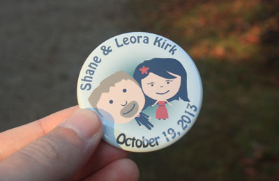
You can see a finished magnet below.

Cake Topper

A month or so later we were brainstorming cake topper ideas. At this point, we still hadn’t seriously considered trying to create our own. I spent a few nights looking around online to see what was out there. But nothing spoke to me. We had already used Leora’s artwork twice. So it had unintentionally become a theme of sorts. It didn’t take long before I became fixated on the idea of turning it into a cake topper.

My idea was simple – create a 3D version of the 2D artwork and then have it 3D printed and painted. A no-brainer, right? 🙂 Well, there were three problems with this idea – 1) My 3D modeling experience was EXTREMELY limited, 2) I didn’t have access to a 3D printer, and 3) I wouldn’t know how to print a 3D model even if I had access to a printer. An ordinary person would probably see these issues as serious impediments and direct their time and money towards more important things. Me? I saw 4 months that could be used for problem solving.

It’d been years since I had done any 3D modeling. Most of my experience came from modeling simple objects for use in experimental OpenGL projects in years past. But I figured that by using the vector artwork to guide the modeling process, I might actually be able to pull off a design in a reasonable amount of time that could pass for original. And that was kind of how I sold it to Leora. I asked her to give me two weeks and if I couldn’t do it in that time frame, we’d go another route.

So I pulled out my trusted, OLD version of 3DSMax and imported the Illustrator files. The Max-fu came flooding back to me. With the outlines to guide me I was able to create the basic shapes for the figurines out of primitives. Using vertex editing mode with soft selection, I was able to “flesh” out models over the course of a week fairly easily.

Now I needed to get the thing 3D printed. Shapeways.com helped me out with that. If you’ve used online photo printing services like Ofoto.com, KodakGallery.com, and Shutterfly.com, Shapeways is kind of like that. But instead of printing photos, they print models. You upload your 3D models to them, pick the material you want to use, and they handle the rest.

Before you upload your models, you have to verify that they’re watertight. Conceptually, that means if the model were to be filled with water, would it leak anywhere? In other words, are there holes (intentional or otherwise)? The tool they recommend for checking this is called AccuTrans3D. AccuTrans3D is primarily a tool for converting from one model format to another. It has a ton of great features, including the watertight test. And the demo version of the software, which only works for a limited time, was enough to test out my work. Shapeways even has a little AccuTrans3D tutorial on their site to help you check your model over. Despite the simplicity of my models, AccuTrans3D actually caught a few problems which, of course, required some rework in Max.

The first time I uploaded my 3 models to Shapeways, I was puzzled. On the website, the models appeared severely faceted. I was convinced that I had done something very wrong and that my inexperience was going to result in some ugly figurines.

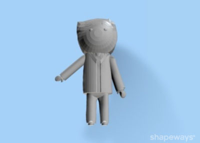
To make matters more confusing, when I viewed them in Max or AccuTrans3D, the models appeared very smooth.

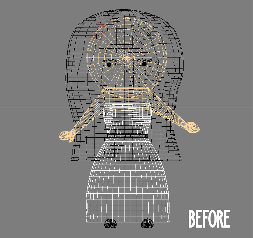
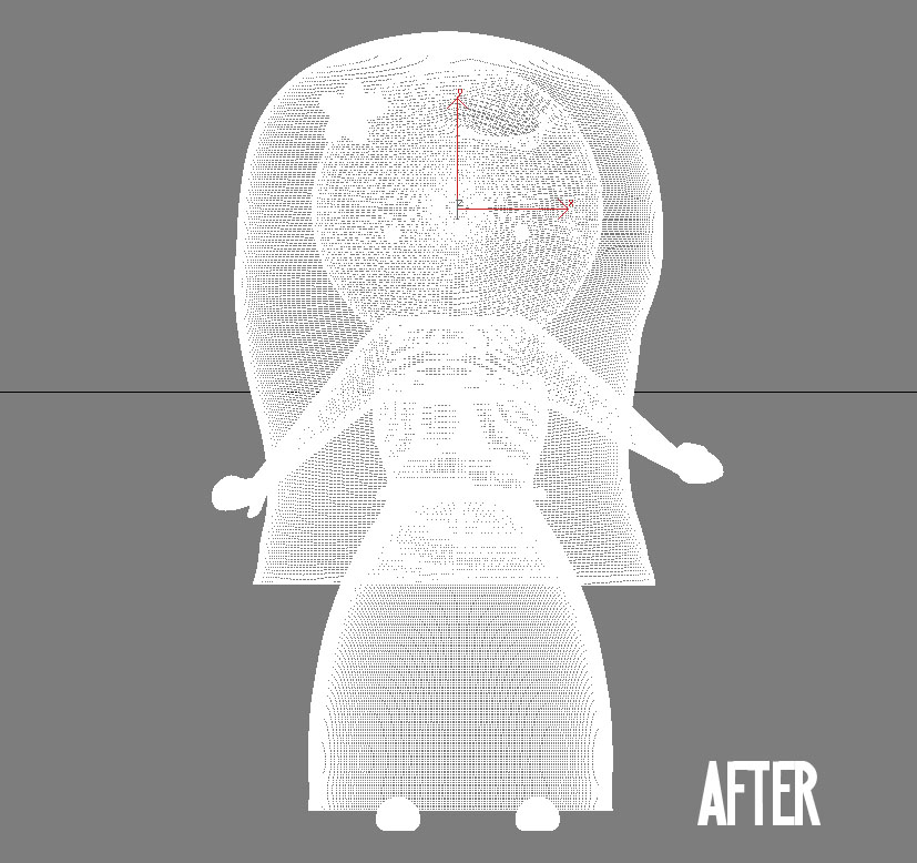
After some time poking around on forums and blogs, I learned that most modeling tools perform smoothing as part of the rendering process. It’s a post-processing kind of thing. This is why my models always look good on the screen. 3D printers are dumb devices and don’t support this kind of magic internally. So I needed to figure out how to smooth out the models manually.

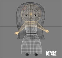
The solution for this is surface subdividing. It increases the complexity of the model by increasing the number of vertices used to represent it. If the subdivision is done right, you can make a model’s surface appear to have the same smoothness you see during the rendering process. 3DSMax has a couple of modifiers that make this easy to do. I chose to use TurboSmooth. Here you can see a before and after wireframe.


It didn’t take me long before I realized doing this consumes vast amounts of memory. The resulting file also becomes monstrous in size. My first few passes at using TurboSmooth resulted in repeated 3DSMax crashes and a file size that exceeded Shapeway’s file size limit of 64MB by hundreds of megs.

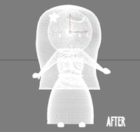
Once I managed to get TurboSmooth under control, I reuploaded my models to Shapeways. The preview looked a lot better as you can see.

It cost me right around $100 to print all three pieces. The pricing is based on the type of material you use and how much is needed. We used their “White Strong & Flexible” material, which is a type of nylon. The turn around time was about two weeks, which was fairly impressive all-considering. When they finally arrived, they looked like this.

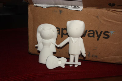
They were kind of heavy for their size. And because they were extremely porous, they had a weird chalky feel to them.


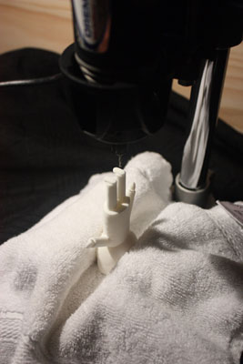
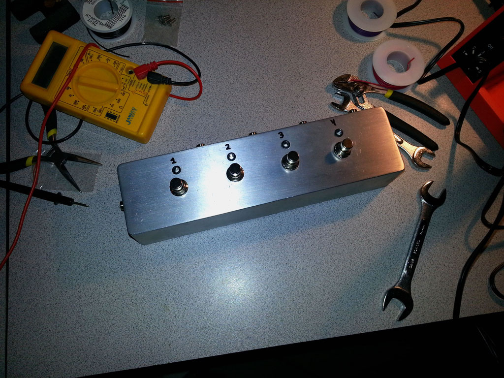
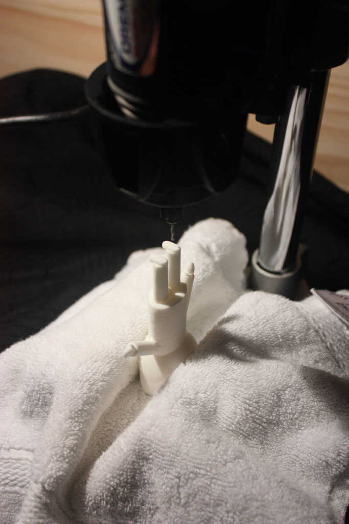
Before we began painting them, I wanted to solve the mounting issue. I had planned on attaching them to some sort of platform with finishing nails. All of the Star Wars action figures I played with as a kid had holes on the bottom of their feet that allowed them to be attached to various playsets. I thought that might work here. So I pulled out my Dremel drill press and went to work.

The thing about drilling plastic is that you have to be fast about it. If the drill bit spends too much time in the hole, the plastic heats up and starts to melt. It’ll coat the drill bit and the hole itself will end up wider than you had intended. This was how the first hole ended up. I inserted a finishing nail as a test and it was extremely loose. The next three holes I was a bit quicker with, and the finishing nails fit nice and snug.

Now we were just about ready to paint.

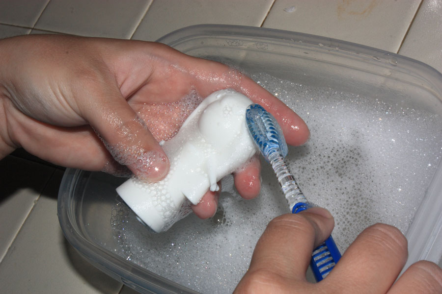
Before we went any further, we washed the models to remove any residual oils and residue left over from the printing process. We stuck them in a tupperware container with water and dish soap and then gave them a light scrubbing with an old toothbrush.

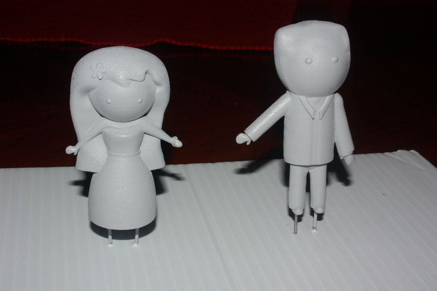
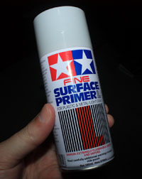
Next, it was time to prime the models. As I mentioned, they were extremely porous. If we had simply applied paint, I’m pretty sure the model would have soaked it up in weird ways and it would have looked uneven. I picked up a can of gray Fine Surface Primer from Tamiya America and over the course of the next few days, we applied around 7 light coats. The end result was much, much smoother.


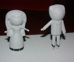
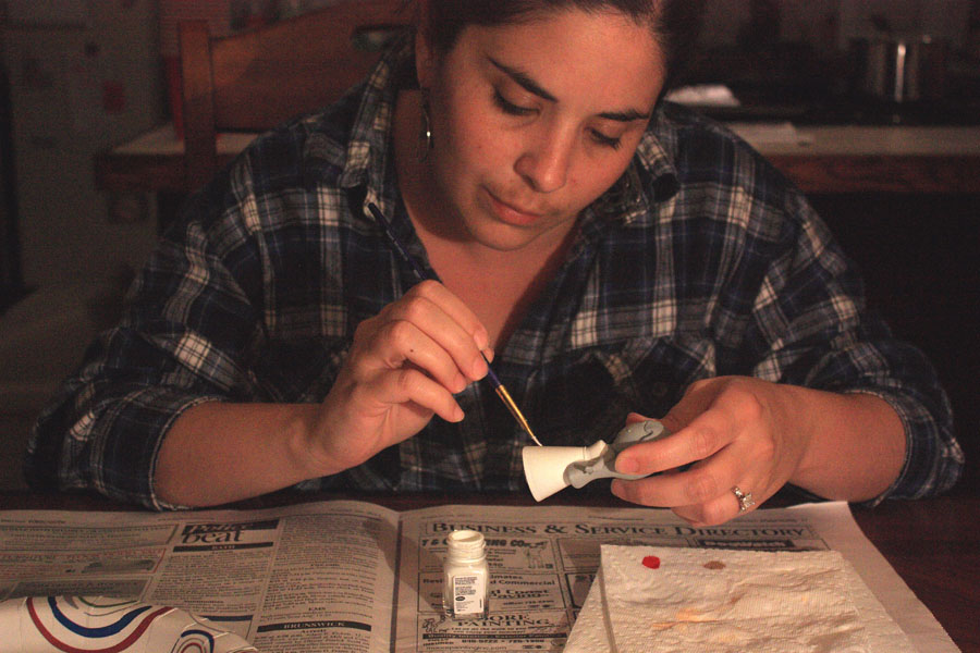
Leora and I had a really difficult time finding flat enamel paints in the colors we wanted. Surprisingly, the Internet wasn’t much help. I checked out online hobby shops, Amazon, ebay, etc. And pickins’ were slim. As a last resort, we visited our local hobby shop, Ray and Robin’s and, as luck would have it, found exactly what we needed. We came home with an assortment of flat enamel paints from Testors.

Now it was time for Leora to do her magic.

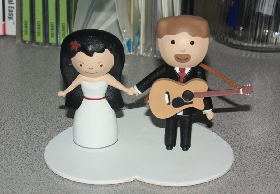
After they were painted, we glued on the guitar using some Loctite glue for plastics. We also hot-glued on a little guitar strap. We found a little heart-shaped wooden platform at one of the local craft stores and this was the end result.

Was it a lot of work? Heck, yeah. But it was also a lot of fun and extremely challenging. Leora and I both stepped outside our creative comfort zones on this one. But the cake topper turned out great. And I’m sure we’ll cherish it for the rest of our lives.

Creating Flat Packages in OSX

I was recently involved with a daemon-style Java project that needed a simple installer solution for OSX. We didn’t require a huge amount of sophistication from the installer. So we opted for flat packages. Flat packages are simple, self-contained files that are easy to pass around.

Prior to Leopard (10.5), packages weren’t flat at all. They were bundles, which are just folders that OSX treats in a special way. Bundles contain a variety of files. Package bundles, for example, contain files used as part of the install process such as a bill of materials, the application payload, and a collection of localized resources among other things. Previously, if you wanted to distribute one of these packages, you’d have to put the package inside a DMG or tar it up.

Another interesting thing happened during the evolution of OSX packages. PackageMaker, a wart in the eyes of many developers and source control systems, was officially deprecated and dropped in Xcode 4.6 (and there was much rejoicing :-)). Developers were left with three terminal-based utilities that could be used to build packages – pkgbuild, productbuild, and pkgutil.

For more information on the evolution of OSX packages, I highly recommend reading this MacTech article which goes into the subject in some depth.

pkgbuild

pkgbuild is a tool for creating a very basic, bare-bones component package. The resulting package will contain the payload for a single component. It also supports preinstall/postinstall scripts. And that’s about it.

productbuild

productbuild is a tool for creating a “product archive”, which is kind of like a super-package. I like to think of it as a package of packages. But it’s really so much more. You can customize the UI, as well as explicitly declare installation prerequisites such as the minimum required RAM, OS version, etc. Even JavaScript is supported for some things. If you create apps for the Mac App store, this is the tool you’ll be using to build your packages.

pkgutil

pkgutil is kind of like a Swiss Army knife for packages. With pkgutil, you can rip a package apart and then put it back together again. It doesn’t matter if it’s a product archive or a component package. If it’s a pkg file, pkgutil can work with it. It also provides a number of options for examining package contents and performing tasks like package verification and repair.

I’m going to give a quick overview on how I use these three utilities to build the flat package for our product. This approach can be adapted for your own needs.

Simple Component Packages

If you want to create a very simple package for a single component application, the easiest tool for the job is pkgutil. A complete list of options for pkgutil can be found on the man page. But here are the ones that are important.

--root – This option specifies the location of the source content you want packaged up. This can be a path containing anything. Our own application is Java-based and is nothing more than a folder of JAR files. We simply point --root to the folder containing all of our JAR artifacts.

--component – You can use this option as an alternative to --root. With --component, you’re being a bit more specific by giving pkgbuild the path to a component bundle. This might be an app bundle, a browser plugin bundle, etc. Why would you use this option instead of --root? If pkgbuild knows it’s working with a bundle, it can infer some of the other configuration options it needs, such as package identifier and install location.

--identifier – The identifier is a unique string that identifies your component. The normal convention for the identifier resembles something like a backwards domain. You start with a TLD, then follow that with a company name or developer name, and then follow that with a product name. So an identifier for Roadie Assist (not an iOS or OSX app, but could be someday) might look like “com.shanekirk.roadieassist” (this is indeed the package name on the Google Play store). There’s certainly flexibility in how you name your package IDs. They just need to be unique. But don’t deviate too much from the convention. It’ll only cause confusion.

--version – This is a monotonically increasing number. The idea is that every time you release a new version of the component, you need to increase this value. Otherwise, the upgrade process may fail. If this value isn’t set, pkgutil defaults with a value to 0. (Tip: If your build system keeps track of build numbers, consider using that as your package version. If the whole thing is automated with scripts, you’ll probably never have to think too much about this value again.)

--install-location – This is where you want to place the component on the target system. For instance, if you’ve built an application bundle, you’ll probably want to place it in /Applications on the target machine.

--scripts – Packages support a number of scripts that are invoked during the install process. If you have a script called preinstall, this will be invoked before the component is installed. If you have a script called postinstall, it will be invoked after the component is installed. The --scripts option specifies where you’re storing these scripts. The scripts can be in any language so long as the files are marked executable and have the appropriate shebang indicating the path to the interpreter. If either of the scripts return a number other than 0, Installer assumes a failure occurred and the installation halts.

A typical invocation of pkgbuild might look like so…

pkgbuild --root ./stagedfiles --scripts ./scripts --identifier com.example.myapp --version 1 --install-location /Applications mypackage.pkg

For many folks, this may be all that’s needed. From within Finder, you can double click the resulting package and component can be installed without having to do much else. If you would like to customize the UI a bit, allow for a more “componentized” installation, or distribute your application through the Mac App store, you’ll need to use productbuild.

Product Archives with productbuild

Much of what you can do with pkgbuild you can also do with productbuild. But don’t be fooled. Product archives and component packages aren’t quite the same thing. Synthesizing a distribution from a product archive (package created with productbuild), for example, will fail, but doing the same thing with a component package (package created with pkgbuild) works just fine (have no idea what I just said? Don’t worry. You will soon.) With productbuild, you can also customize quite a bit of what the end user sees. If you peruse the man page for productbuild, you’ll find that many of the command-line options you used with pkgbuild are there for productbuild as well. But you’ll also see a few other things mentioned like plugins, distribution files, resource folders, etc.

Regardless of how you created your package, you’ll probably want to update the UI or perform more sophisticated prerequisites checking. To do this you’ll need to create a distribution file.

A distribution file is just an XML file. It’s used to configure both look and feel, as well as behavior, of the package installer. The idea is that you create this file and then use productbuild to create a new package from the old one and the new distribution file. Confused yet? Let’s work through an example.

productbuild example

Let’s assume we have a package called mypackage.pkg kicking around (if you’re reading closely, you’ll notice this is the same package I use as an example above while discussing pkgbuild.). Our goal is to change the title and background image shown to the user. So we need to create a distribution file and modify it to suit our needs. Fortunately for us, productbuild is able to synthesize a skeleton distribution file for us.

productbuild --synthesize --package ./mypackage.pkg distribution.xml

Note that this only works against component packages created with pkgbuild. If you try to do this against a pkg created by productbuild, it’ll result in an error. The resulting XML will look something like the following.

<?xml version="1.0" encoding="utf-8" standalone="no"?>
<installer-gui-script minSpecVersion="1">
    <pkg-ref id="com.example.myapp"/>
    <options customize="never" require-scripts="false"/>
    <choices-outline>
        <line choice="default">
            <line choice="com.example.myapp"/>
        </line>
    </choices-outline>
    <choice id="default"/>
    <choice id="com.example.myapp" visible="false">
        <pkg-ref id="com.example.myapp"/>
    </choice>
    <pkg-ref id="com.example.myapp" version="1" onConclusion="none">mypackage.pkg</pkg-ref>
</installer-gui-script>

So far, so good. Let’s first change our package title. We want the title to be “My Example Application”. Open the distribution XML with your favorite text editor. Within the installer-gui-script element, create a new child element called “title” and set the element’s character data appropriately. It should look something like this.

<title>My Example Application</title>

Now let’s create a new background image for our installer. The recommended size for the background image is 620×418. The background image I’ll be using for this is example is a simple PNG as shown below.

Create a new folder for your installer resources and place the image in there. We’ll call it the file background.png.

Now, let’s add the PNG reference to the distribution.xml. Open the XML file and within the root installer-gui-script element, create a new element called background. Add two attributes, one called “file” that simply names the file and one called “mime-type” that describes the image type. For example, your background element might look like so.

<background file="background.png" mime-type="image/png" />

Save your changes. Now we just need to create a new package with our modified distribution file. Using productbuild the command might look like so.

productbuild --distribution distribution.xml --resources ./myimages --package-path ./mypackage.pkg myimprovedpackage.pkg

This command produces a new package called myimprovedpackage.pkg that has the new modified background image. If you double click on it with Finder, you should see your new background image, but it should also install the new package just as it did the old one.

For a complete list of everything you can do to a distribution.xml, check out the distribution xml schema reference. You’ll find that there’s a lot of flexibility in what you can do to your packages. There are some things I always do, such as customize the welcome, license, readme pages, run JavaScript as part of the startup validation, and limit install locations to the root volume. But I’ll save discussion of those types of things for a future blog post.

Injecting Files Into Flat Packages

At some point in your journey with flat packages, you’ll find that you can’t get something into the package file that you really think should be there. This might be an extra script or even an Installer plugin (a topic that deserves its own blog entry). Both pkgbuild and productbuild promise to copy content out of the scripts or resources folders, but sometimes they just don’t. So we need to get these files into our package. That’s where pkgutil comes in.

pkgutil allows you to expand a package to a folder structure like so.

pkgutil --expand myimprovedpackage.pkg expandedcontent

This creates a folder called expandedcontent that contains the expanded content of the package. If you explore the folder structure, most of what you see will only make sense if you’re familiar with the structure of the original package bundles. I strongly advise you to read up on the history of the package format I mentioned in the beginning to be effective at shuffling stuff around within these folders.

Once you’ve got things where they need to be, then you can flatten everything again like so.

pkgutil --flatten expandedcontent myimprovedpackage.pkg

Conclusion

And that’s it. I realize I glossed over a lot of interesting stuff with regards to the distribution XML file. Experiment with it. I hope to write a followup to expand on some of these topics in closer detail. If you have questions, post them!