In the first article of this series, I spent some time looking at the DFPlayer – a small, affordable MP3 playback device. I demonstrated how it can be connected to an Arduino and driven over a serial connection. In the second article of the series, I looked at RC radio controllers and how they can also be used in an Arduino project. In this final article, I’m going to be combining the concepts from the previous articles to construct a sound board that allows me to trigger audio playback through a radio controller. This will provide an audio solution for a robotics project that my daughter and I worked on together a few months ago.
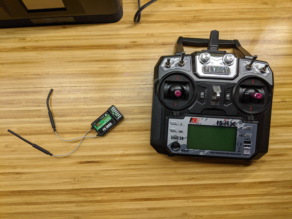
There’s not a whole lot of theory here. I’m going to assume that you’ve read the previous two articles. If something is confusing, or if it seems like I skipped over an explanation, please go check out Digital Audio With the DFPlayer and Radio Controllers With Arduino. If something still seems missing, please reach out to me and I’ll fix it.
Physical Construction
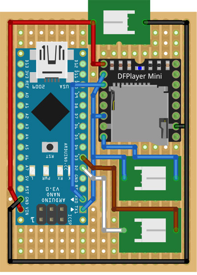
Let’s start by seeing how I wired everything together. Below is a quick layout I did with Fritzing.
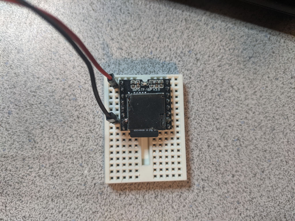
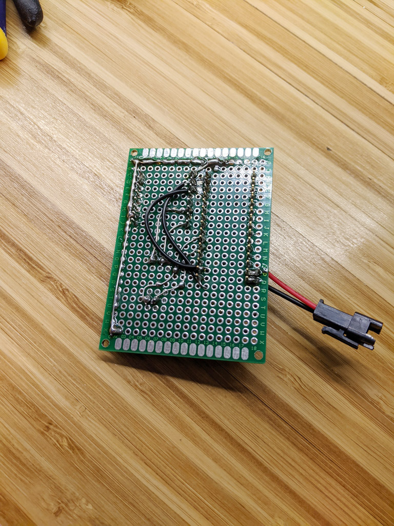
And here is what the actual board looked like when I was finished.
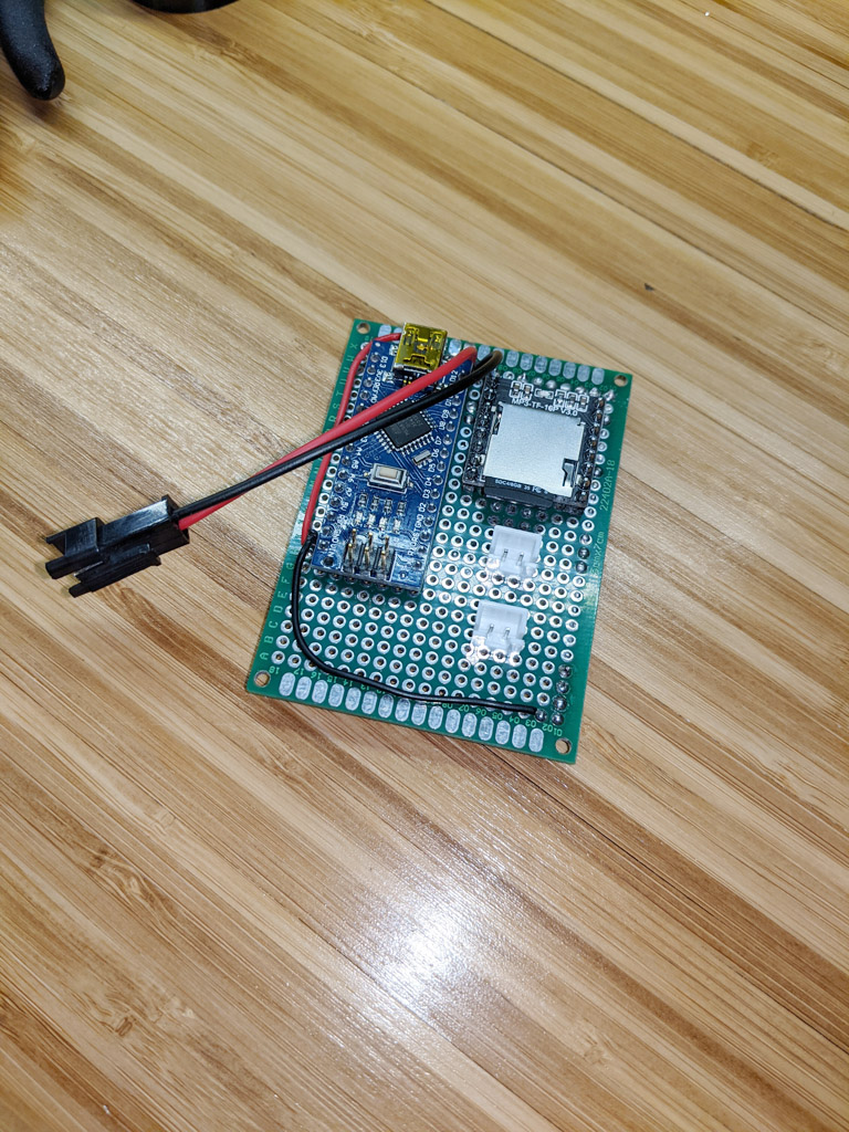
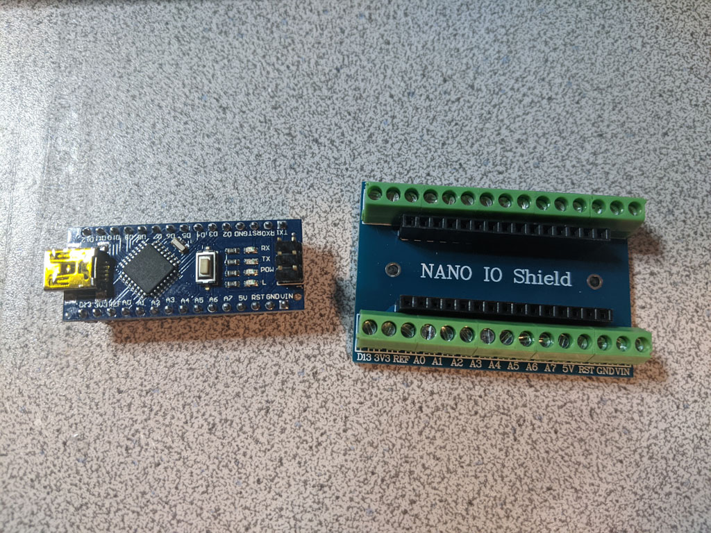
The biggest component on the board is an Arduino Nano.
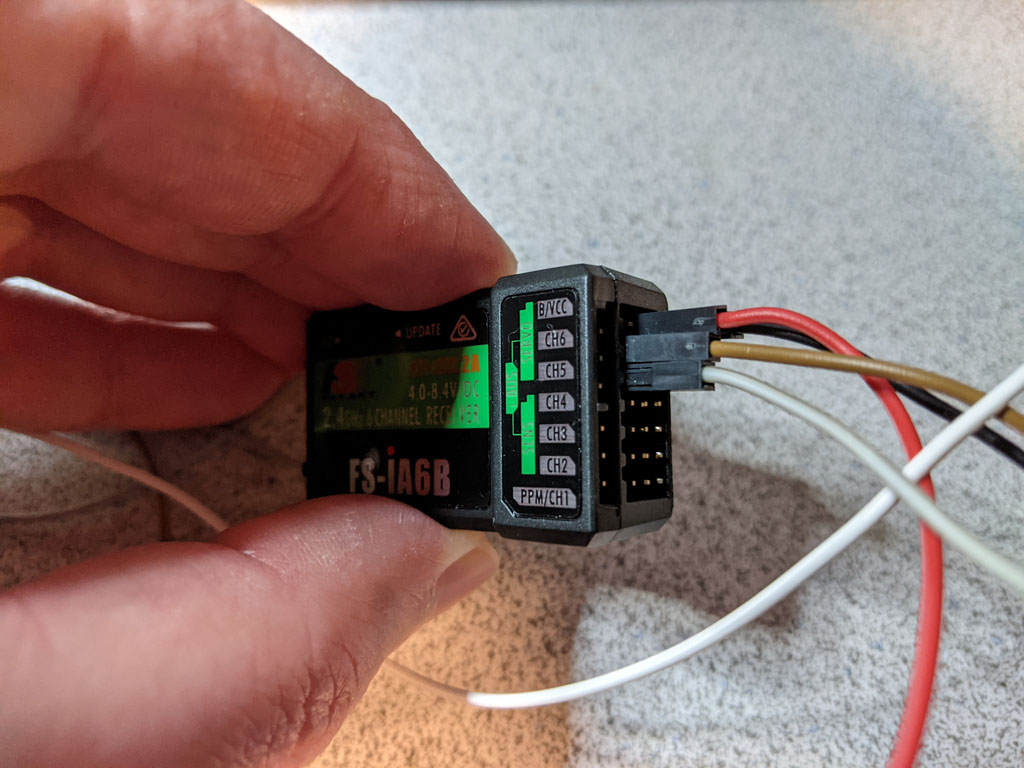
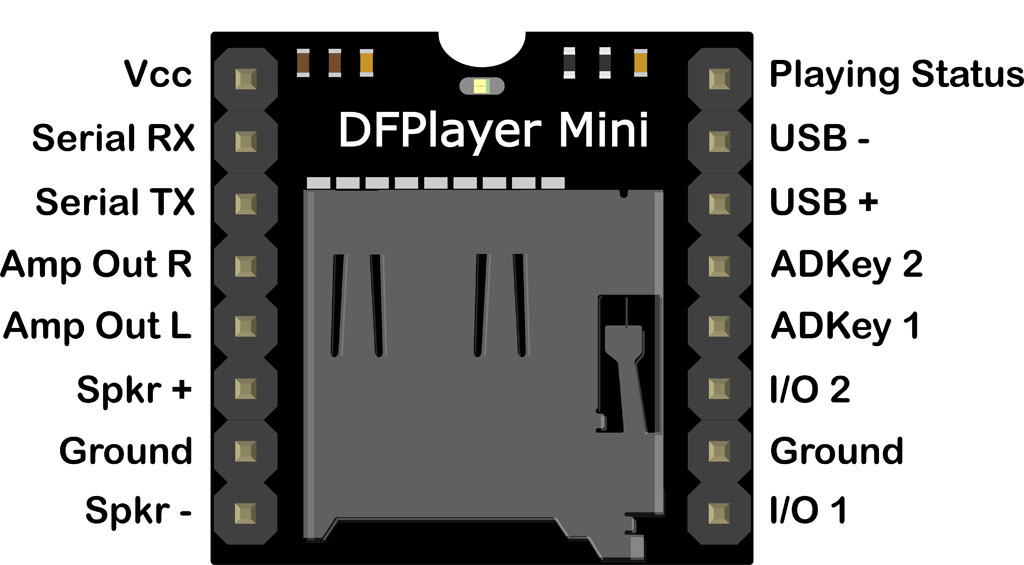
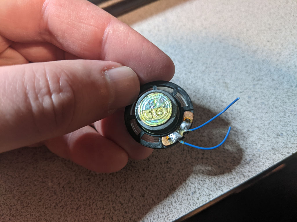
Next to the Nano is the DFPlayer. Soldered to the top of the board is a connector for power. And beneath the DFPlayer are two 2-pin JST connectors. One of the JST connectors is for the speaker and the other is for the PWM data from the RC radio receiver.
I used a solder bridge to connect the components where I could. And where I couldn’t, I added some bridge wire.
If you read my DFPlayer article, you might note a difference in serial connections here. Originally, I had opted for a software-based serial connection from the Nano to DFPlayer using pins 10 and 11. I tried that arrangement here, but then the DFPlayer started locking up frequently when triggered from the radio. I thought there might be some timing/buffering issues at play, so I switched to the hardware UART, which requires use of the RX and TX pins on the Nano. And the problem went away. I’m still not convinced I understand why. I’ll save this investigation for another day. Using the RX and TX pins, however, means I can’t write new code to the Nano without disconnecting the DFPlayer first (e.g., desoldering). I shouldn’t need to do that unless I want to add new functionality down the road.
The Code
What follows is the code I wrote that ties everything together. Because we already saw how much of this works in the first two articles, I’m not going to explain the code line-by-line. I’ll instead give you a quick tour of the functions of interest, as well as a high-level overview of what they’re trying to accomplish.
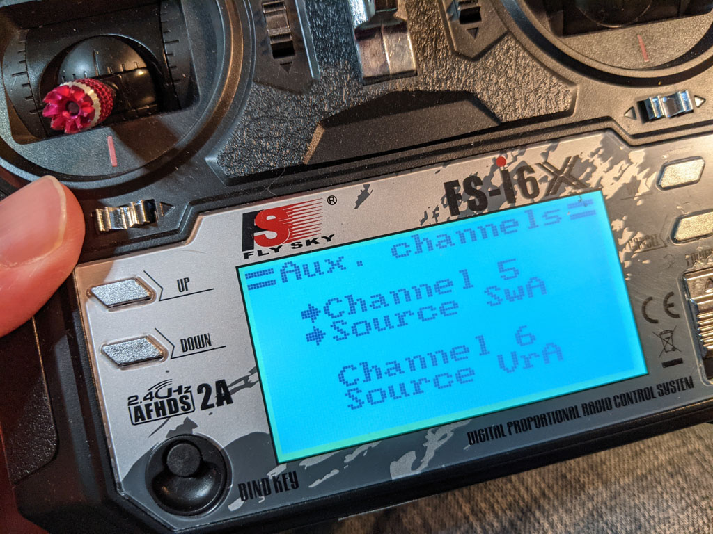
#include "Arduino.h" #include "DFRobotDFPlayerMini.h" // These are connected to RC channels 5 and 6, respectively. static const int AUDIO_TRIGGER_PIN = 2; static const int VOLUME_KNOB_PIN = 3; // For serial communication to the DFPlayer. static DFRobotDFPlayerMini g_dfPlayer; // The total number of files on the DFPlayer's SD card. static int g_totalFileCount = 0; /** * Checks to see if anything has changed on the audio trigger * channel. And if so, plays the next sound. */ void handleFilePlayback() { static int lastTriggerValue = 0; static int lastFilePlayed = 1; int pulseValue = pulseIn(AUDIO_TRIGGER_PIN, HIGH); if (pulseValue == 0) return; int audioTrigger = (pulseValue < 1500) ? 0 : 1; if (audioTrigger != lastTriggerValue) { g_dfPlayer.stop(); delay(200); if (lastFilePlayed >= g_totalFileCount) { // We've already played the last file. Time to loop back around. g_dfPlayer.play(1); lastFilePlayed = 1; } else { g_dfPlayer.next(); ++lastFilePlayed; } delay(200); lastTriggerValue = audioTrigger; } } /** * Checks to see if anything has changed on the volume adjustment * channel. If so, adjusts the volume on the DFPlayer accordingly. */ void handleVolumeAdjustment() { static int lastVolumeValue = 0; int pulseValue = pulseIn(VOLUME_KNOB_PIN, HIGH); if (pulseValue == 0) return; int volumeKnob = map(pulseValue, 990, 2000, 0, 30); if (volumeKnob != lastVolumeValue) { g_dfPlayer.volume(volumeKnob); lastVolumeValue = volumeKnob; } } /** * Enters into an endless loop, flashed the specified * LED at the specified rate. */ void haltAndFlashLED(int ledId, int flashRateInMillis) { bool ledOn = false; unsigned long timeLastToggled = millis(); do { unsigned long currTime = millis(); if ((currTime - timeLastToggled) > flashRateInMillis) { digitalWrite(ledId, (ledOn ? HIGH : LOW)); ledOn = !ledOn; timeLastToggled = currTime; } delay(0); } while(true); } void setup() { // We'll use the built-in LED to indicate a communications // problem with the DFPlayer. pinMode(LED_BUILTIN, OUTPUT); digitalWrite(LED_BUILTIN, LOW); pinMode(AUDIO_TRIGGER_PIN, INPUT); pinMode(VOLUME_KNOB_PIN, INPUT); // Let's give the DFPlayer some time to startup. delay(2000); Serial.begin(9600); if (!g_dfPlayer.begin(Serial)) haltAndFlashLED(LED_BUILTIN, 1000); g_totalFileCount = g_dfPlayer.readFileCounts(DFPLAYER_DEVICE_SD); if (g_totalFileCount <= 0) haltAndFlashLED(LED_BUILTIN, 500); // Valid values for volume go from 0-30. g_dfPlayer.volume(20); // Plays the first file found on the filesystem. g_dfPlayer.play(1); } void loop() { handleFilePlayback(); // Consumes any data that might be waiting for us from the DFPlayer. // We don't do anything with it. We could check it and report an error via the // LED. But we can't really dig ourselves out of a bad spot, so I opted to // just ignore it. if (g_dfPlayer.available()) g_dfPlayer.read(); handleVolumeAdjustment(); // Consumes any data that might be waiting for us from the DFPlayer. // We don't do anything with it. We could check it and report an error via the // LED. But we can't really dig ourselves out of a bad spot, so I opted to // just ignore it. if (g_dfPlayer.available()) g_dfPlayer.read(); } |
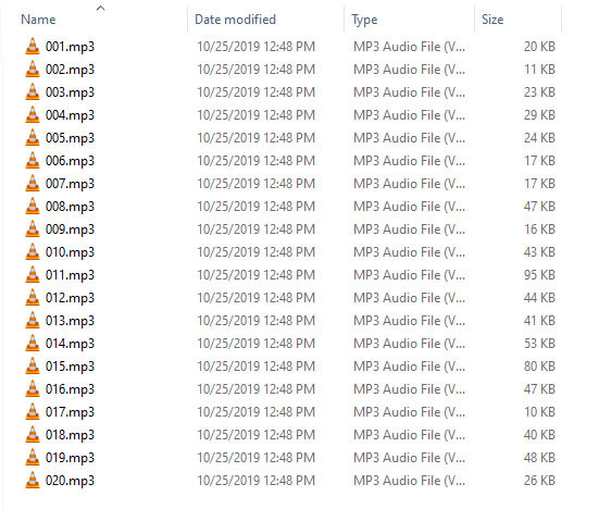
Let’s start by looking at the setup() function. If you’ve read the previous two articles, this should look somewhat familiar to you. We start with initializing pins, the serial port, and the DFPlayer. Something new here is that we query the number of files on the SD card by calling the g_dfPlayer’s readFileCounts() member function. We then cache this value so we later know when to loop back to the first file. If we get a 0 for this value, something is wrong. In that case, we light up the LED and halt. Otherwise, we set the volume to a reasonable value and play the first file.
Next up, let’s look at the loop() function. It’s pretty simple. It just repeatedly calls handleFilePlayback() and handleVolumeAdjustment() over and over.
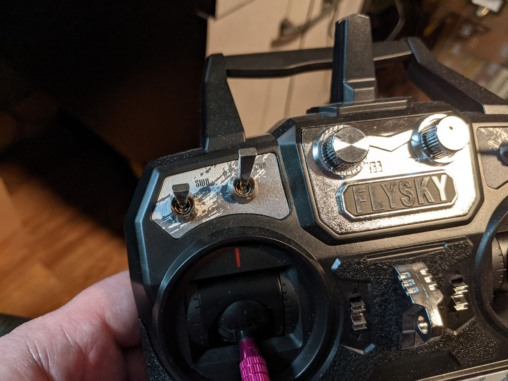
The handleFilePlayback() function is dedicated to checking whether or not the toggle channel value on the RC receiver has changed and reacting appropriately. If the toggle switch hasn’t moved, we do nothing. If it has moved, we then check to see if we’ve exceeded the number of files on the SD card. If we’ve already played all the files, we loop back around to file 1. If we haven’t, then we play the next file.
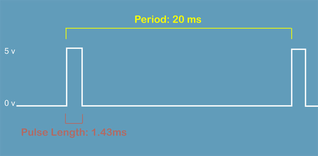
The handleVolumeAdjustment() function checks whether or not the volume knob on the radio has changed value and then reacts appropriately. If the knob value hasn’t changed, we do nothing. Otherwise, we map the PWM value range of 990 to 2000 to the DFPlayer’s volume range, which goes from 0 to 30, and then update the DFPlayer.
Conclusion
And that’s it! All I needed to do after writing the code to the Arduino was connect the speaker, RC receiver, and battery and give it a whirl.
Everything worked great, with one exception. I noticed if my sound board was too near the RC receiver, I started hearing noise in the speaker. For me, it was an easy fix. I just moved the RC receiver further away from the sound board. But if you have a tighter fit, you might need to experiment with shielding.