Radio Controllers with Arduinos

In the previous article, I introduced my need to add sound capabilities to a radio-controlled robot project that I had been working on with my daughter. I focused on the DFPlayer as a potential solution and discussed how to control it using only an Arduino. However, I didn’t discuss radio control at all. Because the DFPlayer discussion was already pretty lengthy, I wanted to defer that discussion and write a separate article for that.

And here we are.

This time around, we’re going focus entirely on radio control. I’ll give a quick primer on how radio control and PWM works. We’ll also learn how to integrate radio control into an Arduino project. By the end, we’ll be ready to combine the concepts introduced in this article and the previous one to produce a radio-controlled audio player. We’ll save the final implementation for a third, and final, article.

Radio Controllers

A radio controller is typically a pair of devices – a radio transmitter and radio receiver. They cover the gamut in terms of cost and functionality. Whether you’re building a drone, an RC car, a robot, or a fun Halloween prop, there are a lot of radio solutions to choose from. For my purposes, I was just adding functionality to a pre-existing project using a radio that was already in use – the Flysky FS-i6x. That’s the radio controller I’ll be discussing here. But the concepts should carry over to pretty much any consumer-grade radio controller you buy off the shelf. I picked up the FS-i6x from Amazon for $59. (Although, at the time of this writing it appears the price has gone up slightly.)
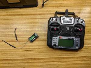
The Flysky FS-i6x is a 10-channel 2.4 GHz radio transmitter and comes with a 6-channel receiver that’s pre-bound to the radio. It supports tank-style channel mixing (after some configuration), a few common stick configurations, and a few extra switches and knobs that can be used for whatever you need.

Channels and Gigahertz, Oh My!

If you’re new to the radio controller world, you may be unfamiliar with the channels and frequency specifications that are used to characterize radio controllers.

The frequency number refers to the frequency band the radio transmitter uses to exchange information with the receiver. For newer RC systems, 2.4 GHz is commonplace. As far as the FCC is concerned, 2.4 GHz is part of the industrial, scientific, and medical unlicensed band. It’s a crowded band that’s shared by cordless phones, Bluetooth, WiFi, baby monitors, etc.

The number of channels a radio controller has refers to the number of separate “features” it supports. Each channel is tied to a separate control on the transmitter and has its own independent data associated with it. If you look at the picture of the transmitter above, you’ll see it has 2 sticks. Each of these sticks is associated with two channels – one for up and down and one for left and right. Each toggle switch is also a separate channel. And each knob is a separate channel too. (2 sticks x 2 channels per stick) + 4 toggle switches + 2 knobs = 10 channels. Other radio transmitters can have support for more channels and others can have less.

How Radio Controllers Work

Off the shelf, consumer-grade radio controllers are typically unidirectional as far as communication is concerned. Data flows from the radio transmitter to the radio receiver. There are some common exceptions to this rule. For instance, receiver-side battery strength and radio signal strength are often transmitted back to the transmitter for the user to monitor. But, in general, data is one way.

The way the data looks as it flows from transmitter to receiver will vary by manufacturer. There are no standards for consumer grade radio controllers that I’m aware of. If your receiver dies and needs replacing, or you simply want to buy another one so that you can use your transmitter in another project, you’ll need to find a receiver that’s compatible with your transmitter (usually from the same manufacturer).

On the receiver side, each channel will have a separate physical connector that can be used to connect to a servo, flight controller, general purpose microcontroller, Raspberry Pi, etc. The data that leaves these connectors is typically delivered as PWM signals.

PWM

PWM stands for Pulse Width Modulation. The idea behind PWM is that we start with a low voltage and periodically pulse a higher voltage for a specific length of time. The length of this pulse is interpreted to mean something. What that something is depends entirely on your application and what you want it to mean.
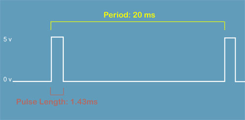
I’ll show some code in a bit that allows us to see the range of PWM values emitted from the FS-i6x receiver.

Assigning Channels for the Sound Control

Channels 1-4 on my transmitter are reserved for the sticks, but channels 5 and 6 can be reassigned. I assigned channel 5 to the first toggle switch, which I’ll be using this to trigger audio playback. And I assigned the first knob to channel 6, which I’ll use to control volume.
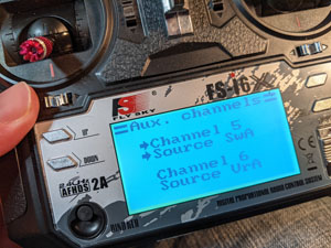
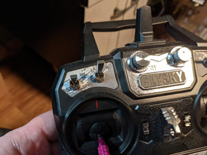
On the receiver side, I just had to connect the signal pins for channels 5 and 6 to something that can read PWM. I connected the signal pins for these channels to the Arduino Nano’s pins 2 and 3, respectively. Pins 2 and 3 on the Nano can be especially useful here because they’re the only two pins on the Nano that support interrupts. At this point, I don’t actually need to use interrupts. I’m undecided if I’ll use them in the final project.

My connections looks like so.
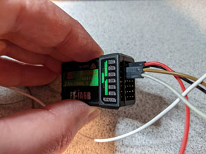

In addition to the channel connections, both the Arduino and the RC receiver are connected to a 5v power source. That’s what the red and black wires coming off both devices are for.

Now it’s time to see some code. For this test, I wanted to make sure that the Arduino is able to read data from the RC receiver, as well as find out the range of values delivered via PWM. The min and max range will be important to know in the final Arduino sketch for my project. My RC test sketch looks as follows.

void setup() 
{
    pinMode(2, INPUT);
    pinMode(3, INPUT);
 
    // For writing to the Serial Monitor on the PC.
    Serial.begin(9600);   
}
 
void loop() 
{
    int audioTrigger = pulseIn(2, HIGH);
    int volumeKnob = pulseIn(3, HIGH);
 
    Serial.print("Trigger value: ");
    Serial.println(audioTrigger);
    Serial.print("Volume value: ");
    Serial.println(volumeKnob);
    delay(1000);
}

Short and sweet.

In the setup() function, I set the pin mode for pins 2 and 3 to INPUT and then set the baud rate for the serial port to 9600. The serial port is only important here for communication with the Arduino IDE’s Serial Monitor. It’s not needed for anything PWM related.

In the loop() function, I call pulseIn() for each pin. I pass HIGH so that pulseIn() measures the time the signal is high. I could have passed LOW in to measure the opposite, if it made sense to do so. This function returns the number of microseconds (not milliseconds) the pulse is in the specified state. After that, I simply send the values over the serial connection for display.

After uploading the sketch and powering everything up, both channels were initially reporting values in the vicinity of 1 ms (1000 microseconds).

Trigger value: 1002
Volume value: 994

When I toggled switch A on my radio, the trigger value jumped within the vicinity of 2 ms (2000 microseconds).

Trigger value: 1994

Since the trigger switch is either in position A or B, I can probably safely assume that any value less than 1.5ms is one value and any value equal to or higher than 1.5ms is the other.

When I turned the VRA knob on my radio, the volume values also began approaching a maximum value of 2 ms (2000 microseconds).

Volume value: 994
Volume value: 1326
Volume value: 1786
Volume value: 1998

Assuming the range is between 990 and 2000, I can map that to the range of values used to adjust the DFPlayer’s volume.

So now I have all the information I need to put together the final sketch, which we’ll do in the next article.

Digital Audio with the DFPlayer

My oldest daughter and I recently built one of Mr. Baddeley’s Baby R2s. These units are small, almost cartoonish, radio-controlled R2D2s that are extremely easy to build. And fun! But something missing from the design (at least at the time of this writing) is the ability for these little guys to produce sounds. And what’s an R2D2 with his signature beeps and boops?

For my life-size R2, I incorporated an MP3 Trigger from Sparkfun and paired that with an Arduino. But I couldn’t use that here because the MP3 Trigger is too large. The Baby R2s just can’t accommodate it. So I went in search of something else. And that’s when I came across the DFPlayer from DFRobot.

In this article (the first of three), we’ll be exploring the DFPlayer and beginning our journey into ultimately using an RC radio to trigger audio. If that’s not something that interests you, no worries. This article is focused entirely on the DFPlayer.

DFPlayer

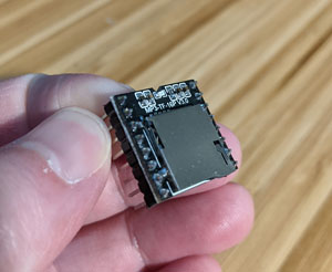
DFRobot’s DFPlayer is a tiny (~ 21mm x 21mm) module that’s capable of playing MP3, WMV, and WAV audio data. It features a micro-SD slot for your audio files. It can be connected directly to a small speaker (< 3 W) or an amplifier. And it can be controlled a few different ways, including via a serial connection which works well for my particular needs.

Perhaps the biggest selling point for the DFPlayer is its price – $6 as of this writing. Compare that to the SparkFun MP3 Trigger, which comes in at around $50. The DFPlayer is practically a guilt-free impulse buy. In fact, I picked up a 3 pack from Amazon for around $10.

One of the downsides to this module is that there are various models that exhibit different tolerances to electrical noise, which means you might struggle with an audible hiss. Killzone_kid posted a great writeup on the Arduino forums that examines some of the models and makes some recommendations on possible ways to mitigate the hiss. Some of the flavors also apparently have compatibility issues with the officially supported DFPlayer Arduino library, which we’ll look at in a bit.

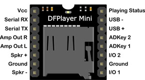
Here’s the pin diagram for the DFPlayer.

Left-Side Pins

There’s a Vcc pin and a ground pin as you might expect. These pins are used to power up the device. The source voltage must be between 3.2V and 5V.

The Serial RX and TX pins are used to provide a serial interface for controlling the device. It defaults to 9600 baud, 1 data bit, no check bits, no flow control. The serial protocol is detailed in the datasheet. But there’s also an official support library for Arduino called DFRobotDFPlayerMini that implements the serial protocol and provides a high-level interface for controlling the DFPlayer.

The Amp Out pins are for connecting to an audio amplifier or headphones.

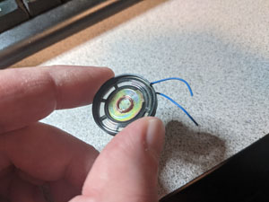
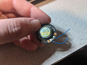
The Spkr pins are for very small speakers – less than 3 watts. This is actually what I’ll be using for my project. I’m connecting the DFPlayer to a small speaker that I harvested from one of my kids’ annoying…er, I mean, broken toys.


Right-Side Pins

On the right-hand side of the pin diagram, you’ll see pairs of pins for I/O and ADKey. These are two other mechanisms for controlling the DFPlayer. We’ll use the I/O pins to test the DFPlayer shortly. But we won’t be using the ADKey pins at all. I won’t be discussing them further. If you want to learn more about them, I advise you to check out the DFPlayer Wiki.

The USB pins allow the DFPlayer to work as a USB device. I haven’t been able to find very much information about this. It’s not discussed much in the DFPlayer manual. Apparently, it provides a mechanism for updating the contents of the SD card from your PC. This could be handy for projects where the DFPlayer ends up hidden away inside of an enclosure that can accommodate a USB connector on the outside. For my project, I don’t need it so I won’t be exploring it. However, if anyone knows where I can find more information about this, please let me know. It could come in handy on another project.

The pin labeled “Playing Status”, referred to as the “Busy” pin, is normally high when the device is idle and goes low when the device is playing audio. The device already has a small LED that lights up when it’s playing files. But if that’s not good enough, you can connect an LED to this pin, or connect it to a microcontroller for more sophisticated behaviors.

Adding Media Files

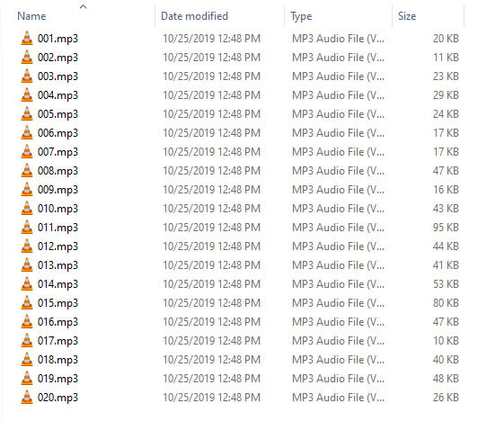
The DFPlayer manual describes the naming of folders and files on the SD card. With regards to files, it specifies names using 3 digit numbers, such as 001.mp3, 002.wav, etc. Folders can be named similarly. I didn’t actually create any folders on my SD card, and it worked just fine. My file layout looks like so.

Testing the DFPlayer

Before doing anything else, I like to do a quick smoke test. This simply involves powering up devices straight out of the box (if feasible) and seeing if any magic blue smoke appears. I also like to note if any LEDs light up, as there’s often a power LED that will indicate the device is at least turning on. In this case, nothing happened. After a bit of reading, I learned that the device’s single LED only lights up when it’s actually playing media. So at this point, I wasn’t sure if it was even powering up. My benchtop power supply said the DFPlayer was pulling a small amount of current, so something was happening.

Next, I wanted to see if I could get some sound out of the device. I plugged in my micro SD card and connected my speaker. The I/O pins (9 and 11) were the key to this. Grounding I/O pin 1 for a quick duration will cause the DFPlayer to play the “next” track. Grounding it for a long duration lowers the audio level. Grounding I/O pin 2 for a quick duration will cause the DFPlayer to play the “previous” track. Grounding it for a long duration raises the audio level.

I grounded I/O pin 2 for a couple of seconds to get the audio level all the way up and then quickly grounded I/O pin 1 with a quick tap. The device’s LED lit up and I immediately heard some beeps and boops. The device was working. Success!

Now I knew any issues I might have trying to drive it over a serial connection would be limited to my code and/or the serial interface itself.

Connecting the Arduino

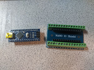
For this project, I used a Nano clone from Lavfin. These come with the pins pre-soldered. When I originally bought this, you could get a pack of 3 from Amazon for around $14. The price has since gone up to $28 as of this writing (presumably, because of supply chain issues).

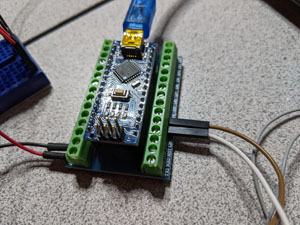
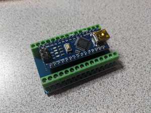
For testing, I’m used a Nano expansion board. This provides convenient screw terminals.


I connected the DFPlayer to the Arduino using the serial pins of the DFPlayer and digital pins 10 and 11 of the Arduino. The DFPlayer’s RX pin connects to the Arduino’s digital pin 11. The DFPlayer TX pin connects to the Arduino’s digital pin 10.

Why didn’t I use the Arduino’s serial pins? I could have. But the process of writing new code to the Arduino makes use of the UART. So I’d have to disconnect and reconnect the DFPlayer every time I wanted to update the software.

I don’t recommend connecting the DFPlayer Vcc and ground pins to the Arduino’s 5v and ground pins unless you REALLY need to leverage the Arduino’s voltage regulator. This is how I’ve seen it wired in the online examples. It’s convenient, sure. But the Arduino has current supply limitations. Having the DFPlayer and the Arduino connected independently to the power source is the better option.

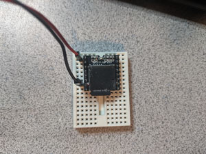
This is how my DFPlayer and Nano are wired together.

The source code for my Arduino/DFPlayer test is as follows.

#include "Arduino.h"
#include "DFRobotDFPlayerMini.h"
#include "SoftwareSerial.h"
 
static SoftwareSerial g_serial(10, 11);
static DFRobotDFPlayerMini g_dfPlayer;
 
/**
 * Called when the Arduino starts up.
 */
void setup()
{
    // We'll use the built-in LED to indicate a communications
    // problem with the DFPlayer.
    pinMode(LED_BUILTIN, OUTPUT);
    digitalWrite(LED_BUILTIN, LOW);
 
    // Let's give the DFPlayer some time to startup.
    delay(2000);
 
    g_serial.begin(9600);
 
    if (!g_dfPlayer.begin(g_serial))
    {
        // There's a problem talking to the DFPlayer. Let's turn on the LED
        // and halt.
        digitalWrite(LED_BUILTIN, HIGH);
        while(true)
        {
            delay(0);
        }
    }
 
    // Valid values for volume go from 0-30.
    g_dfPlayer.volume(20);
    // Plays the first file found on the filesystem.
    g_dfPlayer.play(1);
}
 
// Called over and over as long as the Arduino is powered up.
void loop()
{
    static unsigned long timeLastSoundPlayed = millis();
 
    // We're going to iterate through the sounds using DFRobotDFPlayerMini's next() function,
    // playing a new sound every five seconds.
    if ((millis() - timeLastSoundPlayed) &gt; 5000)
    {
        g_dfPlayer.next();
        timeLastSoundPlayed = millis();
    }
 
    // Consumes any data that might be waiting for us from the DFPlayer.
    // We don't do anything with it. We could check it and report an error via the
    // LED. But we can't really dig ourselves out of a bad spot, so I opted to
    // just ignore it.
    if (g_dfPlayer.available())
        g_dfPlayer.read();
}

To build this sketch, the DFRobotDFPlayerMini library must be installed. This can be downloaded from GitHub –
https://github.com/DFRobot/DFRobotDFPlayerMini. Installing it is as simple as extracting it to the Arduino libraries directory (e.g., C:\Program Files (x86)\Arduino\libraries).

Line #5 creates an instance of the SoftwareSerial class. I call it g_serial. This is used to emulate a UART over digital pins. I reserved the hardware UART so I could update the software on the Arduino while being connected to DFPlayer. If you’d rather use the hardware UART and the Serial global variable, that’ll work fine too. You just have to disconnect the DFPlayer every time you need to update the code. The two arguments to the SoftwareSerial constructor are the pin numbers for RX and TX, respectively.

Line #2 of the source above includes the DFRobotDFPlayerMini header file, which brings the various DFRobotDFPlayerMini types into scope. I then declare the static global instance of DFRobotDFPlayerMini called  g_dfPlayer. This will be the object we use to interact with the DFPlayer.

The first thing the setup() function does is configure the Arduino’s on-board LED. Since I’m not actually using the Serial Monitor in the IDE, I wanted to light this up if there were problems initiating communications with the DFPlayer.

I then delay execution for 2 seconds to give the DFPlayer time to startup. This is important to note because I didn’t see this happen in any of the sample sketches that cames with the DFRobotDFPlayerMini library. Without the delay, things just wouldn’t work for me. I don’t know if it’s because of my particular flavor of DFPlayer and/or Arduino. But 2 seconds seems to be the delay I need to get the devices to talk to one another.

I call begin() on g_serial with an argument of 9600 baud since this is the baud rate supported by DFPlayer. I then attempt to start communication with the DFPlayer by calling g_dfPlayer’s begin() function, passing it the serial object I want it to use. If an error occurs, I light up the LED and effectively halt. If no error occurs, I crank the volume up to 20 (out of 30 max) and play the first file on the DFPlayer’s file system. If all things are well, I should hear a sound.

In the loop() function, we do two things – 1) check to see if it’s been 5 seconds since we last played a sound and, if so, play one and 2) eat up any data sent to us by the DFPlayer. I should point out that I don’t actually know if we need to consume data if we’re not doing anything with it. But without diving too deep into the DFRobotDFPlayerMini code, I’m erring on the side of caution and hoping to keep some buffer somewhere from filling up.

Once this code was compiled and flashed to the Arduino, I had to restart both the Arduino and the DFPlayer. After a couple of seconds, I started hearing more beeps and boops.

Wrapping Up

This code is a good starting point. I encourage you to explore the sample code that accompanies the DFRobotDFPlayerMini library. There are some good nuggets there.

In the next article, I’ll be focusing on interfacing a radio controller with the Arduino. And then a third article will follow that which will tie everything together so that we can trigger our audio with a radio.

Until next time…

GDB Tips and Tricks #6: Examining Data Types

It’s often the case that while stepping through code you encounter a variable that’s unknown to you. If it doesn’t appear to be relevant to the task at hand, perhaps you choose to ignore it. But if it may have some significance to the problem you’re trying to solve, you’ll obviously need to learn a bit more about it.

The first thing you might want to learn about the variable is its type. You can turn to the source code to seek this out. If the type turns out to be a struct/class, typedef, or type alias, you might need to do a bit more spelunking to fully understand what kind of data is in play.

Fortunately, gdb provides us with a couple of commands to help us out when it comes to data types – whatis and ptype

whatis

The whatis command tells us the superficial type of a variable or expression. By that I mean, it will show the type of something as it appears in code. Things like typedefs or type aliases aren’t “unrolled.” But the whatis command accepts expressions too. So if you’d like unroll a typedef or type alias, you can do so manually. Let’s see some examples.

Let’s use the following snippet of code.

struct MyStruct
{
    int x;
    MyStruct() : x(2) {}
};
 
using _IntegerValue = int;
using IntValueAlias = _IntegerValue;
 
int main()
{
    int a = 0;
    IntValueAlias b = 1;
    MyStruct c;
    return 0;
}

After we compile, launch gdb, and step into main, let’s ask gdb to tell us the types of the variables a, b, and c.

(gdb) whatis a
type = int
(gdb) whatis b
type = IntValueAlias
(gdb) whatis c
type = MyStruct

As you’d probably expect, gdb prints “int” when we ask about variable a’s type. When we ask for the type of variable b, we see “IntValueAlias”. You’ll note from the code snippet above that IntValueAlias is just a type alias for another type alias which isn’t shown in gdb’s output. When asked about the type of c, we get the struct name, “MyStruct”.

If we want to dig a bit further on the type alias, we can use whatis like so.

(gdb) whatis IntValueAlias
type = _IntegerValue
(gdb) whatis _IntegerValue
type = int

If you expect whatis to give you more detailed information about structures and classes, you’ll be disappointed to know that it doesn’t help you out. The documentation for whatis actually claims that the /M option will show class methods and that /T shows typedefs defined in a class, but I’ve never been able to get these options to do anything.

(gdb) whatis MyStruct
type = MyStruct

I should mention a couple of things about templates and whatis. The whatis command substitutes template parameters and typedefs when displaying type information for variables of template types. This means you can see pretty nasty stuff.. For example, take this snippet of code.

int main()
{
    std::string a;
    std::map<std::string, std::string> b;
    return 0;
}

If we ask gdb what the type of a is, we’ll see the following.

(gdb) whatis a
type = std::__cxx11::string

That’s not exactly what we typed in our code, but it’s workable.

What about the type of b?

(gdb) whatis b
type = std::map<std::__cxx11::basic_string<char, std::char_traits<char>, std::allocator<char> >, std::__cxx11::basic_string<char, std::char_traits<char>, std::allocator<char> >, std::less<std::__cxx11::basic_string<char, std::char_traits<char>, std::allocator<char> > >, std::allocator<std::pair<std::__cxx11::basic_string<char, std::char_traits<char>, std::allocator<char> > const, std::__cxx11::basic_string<char, std::char_traits<char>, std::allocator<char> > > > >

As my two-year old daughter would say, “YUCK!”. Unfortunately, it is what it is and we have to work with it.

ptype

The ptype command is a bit more heavy duty than whatis. Think of it as whatis on steroids. In the case of typedefs and type aliases, ptype always unrolls them. In the case of structs and classes, ptype gives much more detailed information, which includes methods and member variables. In the case of templates, well, we get a lot more yuck.

Let’s look again at our first example.

struct MyStruct
{
    int x;
    MyStruct() : x(2) {}
};
 
using _IntegerValue = int;
using IntValueAlias = _IntegerValue;
 
int main()
{
    int a = 0;
    IntValueAlias b = 1;
    MyStruct c;
    return 0;
}

Just as we did before, let’s examine the types of variables a, b, and c. But instead of using whatis, let’s use ptype.

(gdb) ptype a
type = int
(gdb) ptype b
type = int
(gdb) ptype c
type = struct MyStruct {
    int x;
  public:
    MyStruct(void);
}

The type of a is shown as int, just as before. The type of b has been unrolled all the way down to the type of the original type alias, which is int. The type of c now shows the layout of the MyStruct struct.

I’ll spare you from a ptype example using templates. As you can imagine, a lot more information is displayed as compared to whatis.

Conclusion

Both whatis and ptype are handy tools for inspecting data types. You could certainly accomplish the same types of things manually within your IDE. But these commands allow you to keep your focus on the debugging session instead of your IDE, which hopefully means being more efficient in tracking down the source of bugs.