I first heard about the Barr Group’s “Embedded Software Training in a Box” at Dan Saks’ CppCon talk “extern C: Talking to C Programmers about C++”. During the Q&A portion of the talk, someone had asked about breaking into the embedded software industry. Dan suggested the Barr Group’s course as a possible first step. I’ve worked in the embedded software world for a while. And I recognize weak areas in my skillset. Always looking for opportunities to learn and improve, I decided to give this course a spin.
The Barr Group’s “Embedded Software Training in a Box” is a cheaper version of their four day, in-person “Embedded Software Boot Camp”. Both courses share the same material and the same exercises, but the boxed kit is self-directed. There is no instructor and no peer support. At the time of this writing, the “Embedded Software Training in a Box” is $899. That’s a whole lot cheaper than $2,399.00, which is what the in-person boot-camp costs – a price difference of about $1500, plus whatever travel expenses you’d otherwise incur.
The Barr Group’s website provides a syllabus for the boot-camp. Major topics you can expect to learn about include idioms for embedded programming with C, memory management, multitasking, and interrupt handling, real-time OS concepts, and a few other odds and ends sprinkled in for good measure.
The Unboxing
The following is a picture of what I received after purchasing the kit.
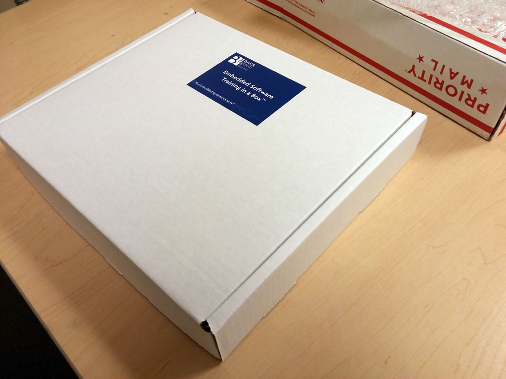
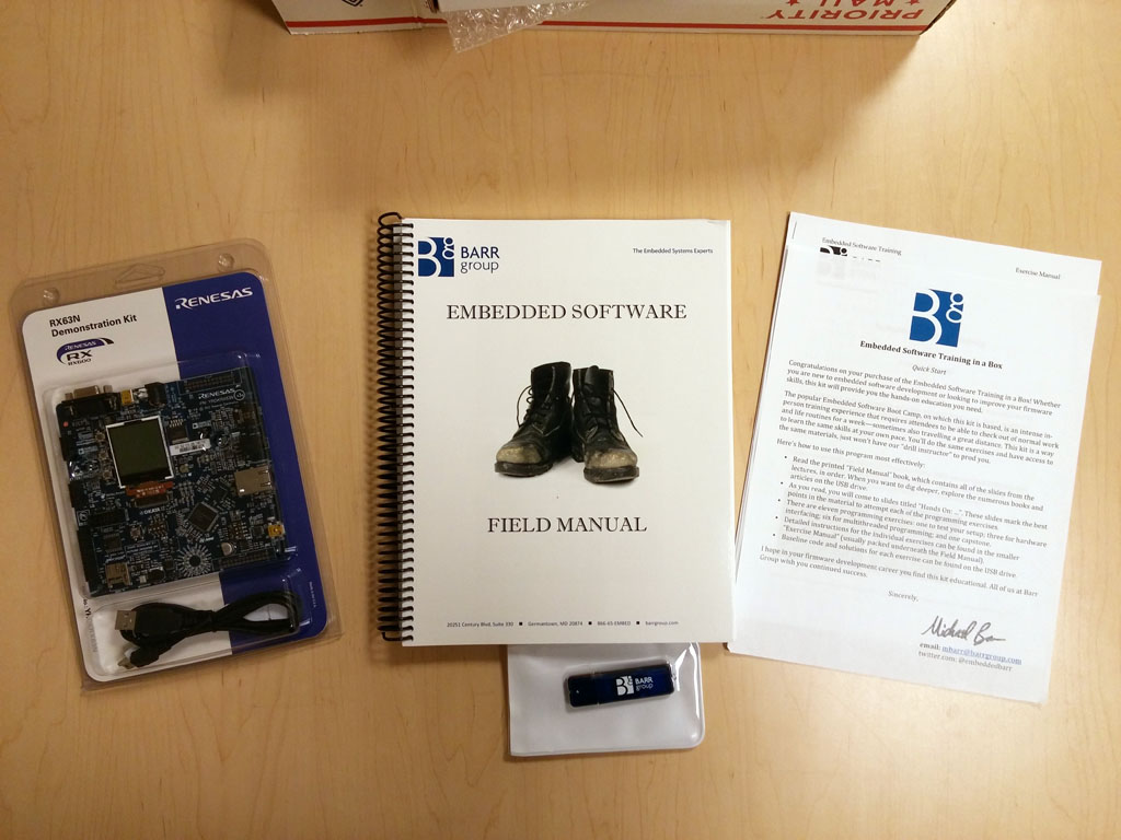
Within the box are five things – an RX63N Demonstration Kit from Renesas, ($105.19 from DigiKey at the time of this writing), a USB drive, an “Embedded Software Field Manual”, an exercise manual, and a quick-start letter.
The “Embedded Software Field Manual” is the cornerstone of this course. It’s intended to be the primary course material. This surprised me, however, as the field manual turned out to be a giant, spiral-bound print-out of all of the slides used in the boot-camp.
The USB drive contains a lot of things, including exercise projects, datasheets, various interesting magazine articles, a few e-books, and the Windows installer for IAR Embedded Workbench 7.0 – the compiler/IDE of choice for this course.
It’s worth noting that a license for IAR Embedded Workbench isn’t provided with the training material. In order to do any of the exercises, you have to obtain a trial license from IAR. Directions are included for how to do this. And there are actually two flavors of the trial license – a time boxed evaluation (30 days) and a code-size limited, time-unlimited evaluation. The training materials instruct you to choose the “Code size limited”, which is plenty sufficient for the exercises in this course.
The way the course works is that you read through the slides until you hit a “Hands-On” exercise. At that point, you’re redirected to the exercise manual which provides more details. Once you’ve completed the exercise, you return to the slides and keep going. Wash, rinse, repeat. There are nine hands-on exercises in total, and a “Cap-Stone” project at the end that’s intended to tie everything together. With the exception of the processor user-manual, the rest of the documentation on the USB drive is supplementary and can be read separately from the course.
Course Pros
- The course covers a wide range of topics, including programming idioms, real-time OS concepts and scheduling algorithms, ADCs, UML state charts, interrupts, multitasking approaches, etc.
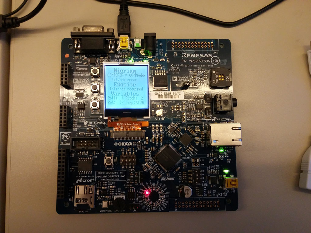
- The Renesas demo board contains a variety of different types of components to play with.
- Getting up and running with the Renesas board and IAR Workbench is super easy.
- There are plenty of good supplementary articles and books provided on the flash drive.
- The flow of the course feels very natural.
- The hands-on projects are somewhat fun. (You can’t go wrong with blinky lights.)
- Solutions to the exercises are provided.
Course Cons
- As I said before, the “field manual” is just a collection of slides. Slides provide talking points. And without discussion around those talking points, a lot of information is lost. The vast majority of the slides are good. But there are a lot of places where more context is sorely needed. Sometimes acronyms are used without being defined, sometimes formulas are defined without any explanation of what they’re used for, and sometimes graphs are included that are just baffling. I confess I had to turn to YouTube at least twice for clarity on a few topics.
- Many of the hands-on exercises are virtually impossible for the uninitiated to complete without looking at the solutions.
- If you’ve never read a data sheet before, you may feel a bit “thrown in the deep end”. The course definitely doesn’t provide a gentle introduction in that regard. When the exercise manual says something like, “Familiarize yourself with such and such 50 pages of the processor data manual”, they really mean read all 50 pages.
- No discussion of embedded Linux.
- The tooling used for the course isn’t cross-platform. It requires Windows.
- No course videos.
- No online forum to discuss material.
Conclusion
This course is just OK, in my opinion. There are definitely some good nuggets of information. The exposure to μC/OS-III was new to me and I enjoyed that. But overall, I was kind of disappointed. The slide format didn’t really work for me. And the exercises, while interesting, sometimes felt a little disconnected from the “field guide” material.
The course could have benefited greatly from some online videos. At the very least, some discussion forums. For a $899 self-directed course this day and age, one expects such things.
The good news is that at the time of this writing if you’re interested in attending the in-person, boot-camp within a month of purchasing the boxed kit, the Barr Group will refund the cost of the kit so long as you bring it with you to the boot camp.
Do I recommend “Embedded Software Training in a Box”? It depends. If the company you work for has a good training budget and is willing to pay for it, sure, go for it. It’s not bad. If you’re paying out of pocket, however, I suggest maybe looking for alternative learning opportunities first.